

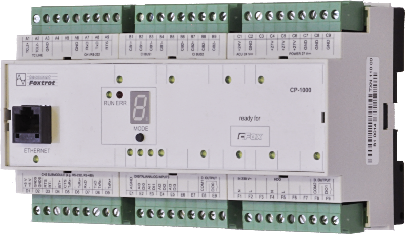

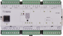

CP-1000TXN 110 00
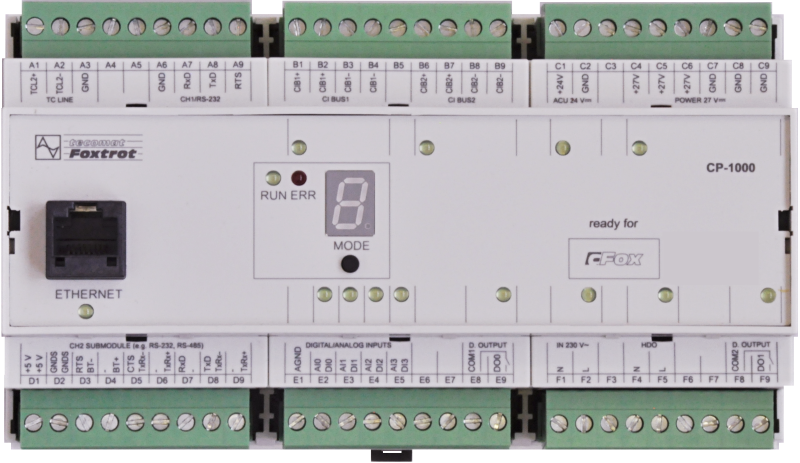
CP-1000, CPU, ETH100/10, 1x RS232, 1xSCH, 4xAI/DI, 2xDI/230VAC, 2xRO, 2xCIB
| DI | 2x DI (230 V AC) |
|---|---|
| DI/AI | 4x DI/AI |
| DO | 2x RO |
| AI | |
| AO | |
| COM | 1x ETH 10/100 1x RS-232 1x free slot for CH2 1x TCL2 master 2x CIB master |
| SENSOR |
| Picture | Variant | Variant description |
|---|---|---|

|
CP-1000 | Application program memory: 192 kB + 64 kB |

|
CP-1001 | Application program memory: 384 kB + 64 kB |
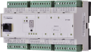
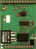
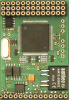
The CP-1000 basic module is one of the basic modules (ZM) of the Foxtrot series modular programmable controller.
The basic module CP-1000 is equipped with:
- four multi-purpose inputs, each of which can be used either as analog or as binary
- two binary inputs at a voltage level of 230V AC
- two separate relay outputs.
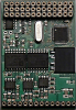
The CP-1000 basic module is equipped with a central unit (CPU) of the K series, which is designed for applications with performance requirements. It contains backed up CMOS RAM for user programs, data, tables, user registers and DataBox, Flash memory for user program backup, slot for MMC / SD / SDHC memory card, real time circuit ,.
It also has an Ethernet interface, two serial channels (one with a fixed RS-232 interface, the other with a position for optional submodules), two communication channels with a CIB interface for connecting external peripherals (2x1A) and a TCL2 system interface for connecting expansion modules that increase number of I / O systems.
The basic module CP-1000 is equipped with:
- four multi-purpose inputs, each of which can be used either as analog or as binary
- two binary inputs at a voltage level of 230V AC
- two separate relay outputs.
The CP-1000 basic module is equipped with a central unit (CPU) of the K series, which is designed for applications with performance requirements. It contains backed up CMOS RAM for user programs, data, tables, user registers and DataBox, Flash memory for user program backup, slot for MMC / SD / SDHC memory card, real time circuit ,.
It also has an Ethernet interface, two serial channels (one with a fixed RS-232 interface, the other with a position for optional submodules), two communication channels with a CIB interface for connecting external peripherals (2x1A) and a TCL2 system interface for connecting expansion modules that increase number of I / O systems.
| Order num. | TXN 110 00 |
|---|---|
| Teco code | TXN 110 00 |
| Categories | Foxtrot 1 - Basic modules |
| Tags | Sales and production discontinued |
| System parameters of the central unit | |
|---|---|
| Row of central unit | K |
| User program memory | 192 + 64 kB |
| Memory for user variables / including RETAIN variables | 64 kB/32 kB |
| Instruction length | 2 ÷ 10 bytes |
| Backup of program source code in PLC | Yes, in program backup memory (EEPROM) |
| On-line program change in PLC | Yes, including I / O configuration change |
| Memory for project archiving - internal | 2 MB |
| DataBox - additional internal data memory | 512 kB |
| Optional memory card slot | SD - Card Slot |
| Cycle time per 1k of logic instructions | 0,2 ms |
| Development environment | Mosaic |
| Programming languages | ST, IL, LD, FBD, SFC, CFC |
| RTC - Real time circuit | No |
| RAM and RTC backup 1) without / with backup battery | type. 500 hr / typ. 20,000 hours |
| Integrated Web server | Yes |
| Integrated Datalogger | Yes |
| Access to PLC variables via web API | Yes |
| Notice | 1) Applies to the basic module without power supply, the backup circuits are disconnected when the power supply is switched on 2) The serial interface CH1 is permanently equipped with an RS-485 interface. The serial interface type CH2 to CH4 is selectable via interchangeable submodules |
| COM - Communication - IP/Ethernet | |
| Ethernet 10/100 Mb (ETHx) | 1 |
| Available system modes on ETH and WLAN | UNI, PC, PLC, PLD |
| TCP / IP protocol | Yes |
| UDP protocol | No |
| HTTP protocol | No |
| WebSocket protocol | No |
| Protocol MODBUS/TCP | No |
| SMTP protocol | No |
| IEC 60870-5-104 protocol | No |
| REST API | No |
| COM - Serial channels | |
| max. number of optional serial channels in the basic module | 4 |
| max. number of expanding serial channels on the TCL2 bus | 6 |
| Number of internal RS-232 serial channels | 1 |
| Available system modes on CH5-10 | UNI, CSJ (CAN) |
| Modbus RTU / ASCII master protocol | No |
| Modbus protocol RTU/ASCII slave | No |
| Profibus DP master protocol (<180 kbit/s) | No |
| COM - System buses | |
| TCL2 - system I/O bus | 1x TCL2 master |
| TCL2 - Range of one branch of the system I/O bus | 10 I / O modules + 4 operator panels + 6 serial channels |
| The communication rate of the system I / O bus | 345 kbps |
| System I / O bus terminating resistor | 120 Ω |
| CIB - Common Installation Bus (R): Installation I/O bus | 2x CIB master (2x 1 A) |
| CIB - Address range of one branch of the installation bus | 32 CFox I/O modules |
| DI - Organization of binary inputs | |
| Total number of binary inputs | 4 |
| Number of groups of binary inputs | 1 |
| DI - Parameters of binary inputs DC (group A) | |
| Number of inputs in group | 4 |
| Notice | Inputs DI0 - DI3 can alternatively be used as analogue inputs (AI0 - AI3). The choice is made for individual inputs from the Mosaic development environment. Due to the possible increase in interference when using analog inputs, it is not desirable to connect the common wire of the binary input switches to the AGND terminal - use GND terminal C. |
| DI - Parameters of binary AC inputs | |
| Total number of binary AC inputs | 2 |
| Organization of binary inputs into groups | 2x (IN230V, HDO) |
| Input voltage for log. 1 | 230 V AC typ., 200 V AC min., 250 V AC max. |
| Input current at log. 1 (typ.) | 5 mA typ. |
| Delay from log. 0 to log. 1 | 10 ms |
| Delay from log. 1 to log. 0 | 10 ms |
| RO - Parameters of binary relay outputs (group A) | |
| Parameters valid for the terminals | DO0, DO1 |
| Number of relay outputs | 2 |
| Number of output groups | 2 |
| Number of outputs in group | 1 |
| Organization of relay outputs into groups | 1x (DO0) +1 (DO2) |
| Output type | electromechanical relay, unprotected output |
| Contact type | NO - Normally Open |
| Diagnose | Alarm signaling on panel module |
| Switching current | 3 A max., 100 mA min. |
| Switching voltage | 250 V AC max., 5 V AC min., 30V DC max. |
| Contact closing time | typ. 10 ms |
| Contact opening time | typ. 4 ms |
| Limit values of switched resistive load | max. 3A at 30 V DC or 230 V AC |
| Switching inductive load limits DC13 | max. 1 A at 30 V DC |
| Switching inductive load limits AC15 | max. 3 A at 230 V AC |
| Switching frequency with rated load | max. 20 switching / min. |
| Mechanical life | min. 5,000,000 cycles |
| Electrical life at maximum resistive load | min. 100,000 cycles |
| Electrical life at maximum load inductive DC13 | min. 100,000 cycles |
| Electrical life at maximum load inductive AC15 | min. 100,000 cycles |
| Short-circuit protection | No |
| Treatment of inductive load | External RC element, varistor (AC), diode (DC) |
| Insulation voltage between outputs and internal circuits | 3750 V AC |
| Isolation voltage between groups of outputs to each other | 3750 V AC |
| AI - Organization of analog inputs | |
| Total number of analog inputs | 4 |
| Number of inputs per group | 4 |
| Number of analog input groups | 1 |
| Organization of analog inputs into groups | 4x (AI0/DI0-AI3/DI3) |
| Common wire | Minus |
| Galvanic separation from internal circuits | No |
| Diagnostics | signaling overload, disconnection and short-circuiting of the sensor in the status word |
| Type of protection | integrated overvoltage protections |
| External power supply | No |
| Digital resolution | 12 bit |
| Converter type | Approximation |
| Filtration | low pass filter, digital comb filter 50/60 Hz |
| AI - Analog Input Ranges (Group A) | |
| Passive sensor | Pt1000, W100 = 1,385 (-90 to +400 °C) |
| Passive sensor | Pt1000, W100 = 1,391 (-90 to +400 °C) |
| Passive sensor | Ni1000, W100 = 1,500 (–60 to +200 ° C) |
| Passive sensor | Ni1000, W100 = 1.617 (-60 to +200 ° C) |
| Passive sensor | Resistance transmitter 0-2 kOhm |
| Passive sensor | Resistance transmitter 0-200 kOhm |
| Passive sensor | KTY81-121; PTC thermistor (-55 to + 125 °C) |
| Passive sensor | NTC Thermistor 12k / 25 °C (-40 to + 125 °C) |
| DI: Voltage-free contact | 0 when> 1.5 kOhm, 1 when <0.5 kOhm |
| Resistance measurement error - maximum error at 25 ° C | ± 0.5% of full scale |
| Resistance measurement error - temperature coefficient | ± 0.05% of full scale / K |
| Resistance measurement error - non-linearity | ± 0.09% of full scale |
| Resistance measurement error - repeatability at steady conditions | 0.07% of full scale |
| Max. permissible permanent overload of analog input (without damage) | –20 to +30 V (each AI terminal against AGND) |
| Detection of disconnected sensor | yes, in status word, range overflow |
| Power supply | |
| Nominal supply voltage (V) | 24 V DC |
| Supply voltage, tolerances | 24 V DC, +25%, -15%, SELV |
| Supply voltage when backing up with an external battery | 27 V DC, +10%, –15%, SELV |
| Typical power input | 10 W |
| Maximum power input | 75 W |
| Module thermal/power loss | 6 W |
| Maximum current consumption (mA) | 3,125 A |
| Galvanic separation of power supply from internal circuits | No |
| Internal protection | Yes, PTC reversible fuse |
| Description of power supply | Difference between typical and maximum power input is given by possible load of CIB buses and number of switched outputs and CPU load |
| CIB branch power supply - parameters of the built-in master | 2x 1 A/ 24-27 V DC |
| Battery parameters | 24 V (2x 12V), max. 18 Ah |
| Continuous charging | Yes, through charging circuitry in the base module |
| Internal protection оf backup battery | Yes |
| Starting from backup battery | No |
| Size and weight | |
| Weight approx. | 300 g |
| Product dimensions (width x height x depth) | 158 x 90 x 62 mm |
| Module width in multiples of M (17.5 mm) | 9M |
| Module width | 158 mm |
| Module height | 90 mm |
| Module depth | 63 mm |
| Product dimensions (width x height x depth) | 158 x 90 x 62 mm |
| Operating conditions, product standards | |
| Product standard | ČSN EN 61131-2:2008 (idt IEC 61131-2:2007) - Programmable control units |
| Protection class of electrical object | II, according to ČSN EN 61140 ed.3: 2016 (idt IEC 61140:2016) |
| IP rating (Ingress Protection) according to ČSN EN 60529: 1993 (idt IEC 529: 1989) | IP20 |
| Operating areas | Normal, according to ČSN 33 2000-3: 1995 (mod IEC 364-3: 1993) |
| Degree of pollution | 1, according to ČSN EN 60664-1 ed.2:2008 ( idt IEC 60664-1:2007) |
| Overvoltage category installation | II, according to EN 60664-1 ed_2: 2008 (idt IEC 60641-1: 2007) |
| Type of device | Module on DIN rail |
| Working position | Vertical |
| Type of operation (operating frequency) | Continuous |
| Ambient operating temperatures | -20 °C to + 55 °C |
| Operating temperature minimum (° C) | -20°C |
| Operating relative humidity | from 10 % up to 95 % without condensation |
| Operating atmospheric pressure | min. 70 kPa (<3,000 m above sea level) |
| Storage temperatures | –25 °C to +70 °C |
| Electromagnetic compatibility, Mechanical endurance | |
| Electromagnetic compatibility / Emission | A, according to EN 55022: 1999 (mod CISPR22: 1997) |
| Emmisions - note | In premises where the use of radio and television receivers can be expected to be used a distance of 10 m from these devices may cause radio interference. In such a case, the user may be required to take appropriate action. |
| Electromagnetic compatibility / Immunity | min. as required by EN 61131-2: 2007 |
| Sinusoidal vibration endurance | 10 Hz to 57 Hz, amplitude 0,075 mm, 57 Hz to 150 Hz, acceleration 1 G (Fc test according to EN 60068-2-6: 1997 (idt IEC 68-2-6: 1995), 10 cycles per axis.) |
| Packaginng, transportation, storage | |
| Description | The module is packed in a paper box according to the internal packing instructions. The package also includes this documentation. The outer packaging is carried out according to the scope of the order and the method of transport of the transport packaging provided with transport labels and other data necessary for transport. Transport of the product by the customer's own means must be carried out by covered means of transport, in a semi-european label on the packaging. The box must be stored in such a way as to prevent spontaneous movement and damage to the outer packaging. The product must not be exposed to direct weathering during transport and storage. Transportation is permitted at temperatures of -25 ° C to 70 ° C, relative humidity of 10% to 95% (non-condensing) and minimum atmospheric pressure of more than 70 kPa. The product may only be stored in clean rooms free of conductive dust, aggressive gases and vapors. The most suitable storage temperature is 20 ° C. |
| Installation | |
| Assembly description | The basic module is mounted vertically on the U-rail ČSN EN 50022. The installation of the assembly (basic module and peripheral modules, if applicable) is performed according to TXV 004 10. |
| Attention! | The device may contain parts with dangerous voltages, covers being removed, or cabling manipulated, or disconnect the appropriate circuits or turn off the power !. |
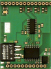
| Exchangeable submodules | The optional MR-01xx submodules with serial channel 2 interface are mounted on the center plate in the CP-10x0 basic module to the position indicated in Fig. 7.1. To add or replace a submodule with a serial channel interface, release the latches on |
| Module operation | |
| Module configuration | The module is operated, set up and diagnosed from the Mosaic development environment. |
| Commissioning | The module is ready for operation after connecting the supply voltage. The MODE button is available on the module panel to display the currently set Ethernet IP address. The parameters of all interfaces are set in the Mosaic development environment. |
| Module diagnostics | The basic diagnostic system of the module is a part of its standard software. It operates from module power on and operates independently of the user. Diagnostic error states of the module and connected peripheral modules of the assembly are signaled |
| Maintenance | |
| Description | The module does not require any maintenance under general installation conditions. |
| Warranty | |
| Generally | Warranty and complaint conditions are governed by the Terms and Conditions of Teco a.s. Notice: Before turning on the system, all the conditions of this documentation must be met, otherwise the protection provided by the equipment may be impaired. The system shall not be escorted unless it is verified and confirmed that the machinery incorporating the Foxtrot system meets the requirements of Directive 89/392 / CEE where applicable. All repairs and servicing of the product are performed exclusively by the manufacturer or by an authorized person. The system installer is responsible for the safety of the system. |
HW documentation
CP-1000 Basic documentation
413.39 kB, (CS, EN)
CP-1001 Basic documentation
235.83 kB, (CS, EN)
User manuals
Foxtrot1 - User's Guide, cze, , TXV00410_01
3.40 MB
Foxtrot1 - User Manual (en), TXV00410_02
4.30 MB
Files for designers
CP-1000 technical drawing DWG
158.77 kB
CP-1000 technical drawing DXF
451.10 kB
CP-1001 technical drawing DWG
154.84 kB
CP-1001 technical drawing DXF
451.86 kB
MR-0124
TXN 101 24
MR-0124, RS-422, with its own power supply and auto-identification, galvanic isolation
MR-0105
TXN 101 05
MR-0105, 1x RS-485, 2x RS-232 (FOXTROT only), GO with its own power supply and auto-identification
MR-0106
TXN 101 06
MR-0106, 2x RS-485, 1x RS-232 (FOXTROT only), with its own power supply and auto-identification, galvanic isolation
MR-0115
TXN 101 15
MR-0115, 3x RS-485, (FOXTROT only), with its own power supply and auto-identification, galvanic isolation

MR-0161
TXN 101 61
MR-0161, 1x CAN (SJA1000, Philips), with its own power supply, galvanic isolation
MR-0160
TXN 101 60
MR-0160, 2x CAN (SJA1000, Philips), with its own power supply, galvanic isolation
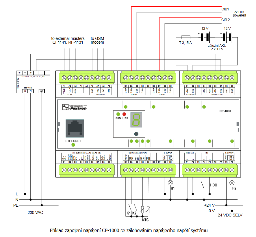
- CP-1000, a power supply with a backup - If the Foxtrot (in this case CP-1000) control system is also utilized for electronic security signalization, it is vital to use a battery backup. The power supply must be able to supply power to the electronic security system in all its modes for t...
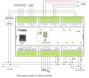
- CP-1000, power supply without a backup - The CP-1000 represents the simplest variant of the basic module for home installations. The basic module is supplied from a 24 VDC source. Both CIB branches (B connector) are supplied from the basic modules, which means that no decoup...
- Connecting a three-command switching element to the CP-1000 inputs - The following figure shows an example of connecting a three-command switching element to the CP-1000 module, which has information on the validity of the low tariff; the power control of the blocked appliances can also be provided directly by contra...
- DMX device control, connection to the CH4 interface of the CP-1000 module - The following example describes the connection of the DMX bus to the CH4 communication interface of the CP-1000 . basic module. In this way it is possible to control up to 512 devices on the DMX bus from the user program of the Foxtrot system. Supp...
- Direct connection of the CP-1000 inputs to the switching element output - The following example shows a direct connection of two-command switching element to the CP-1000 basic module, whose power controls the blocked appliances and which also has information about the validity of the low tariff. The connection covers most...
- CP-1000, CP-1001 - ...from the controlled technology and where is a higher number of peripheral modules on CIB buses, it is preferable to use the CP-1000 basic module. In extensive applications, where complex application software is expected, as well as multiple dev...
- MR-0105, MR-0106, MR-0115, fitted with CP-1000, CP-1001, CP-1003, CP-1091 - Tab. 1: Terminating of CH2, CH3 and CH4 communication channels for CP-10x0 Terminal block D Terminal MR-0105 MR-0106 MR-...
- Energy saver in the hotel room (the card holder) VingCard - ...ning the RFID card holder state can be done by any DI of the Foxtrot system. The 230 VAC inputs (e.g. the CP-1000 ) can be used directly, without a conversion relay, the 230 V input of the CP-1000 module can be connected direc...
- Measurement of 4x 1f production or consumption, electricity meter PA 144 - ...chapter. Fig. 1 Example of connection of 4x measurement of 1f network by electricity meter PA 144 connected to CH2 CP-1000 See this article for wiring notes....
- Foxtrot basic module power supply - ...ing on the type of basic module); without the fitted submodule it is around 2 ÷ 6 W. This does not apply to the basic CP-1000 and CP-1001 modules; for information on their power supply, see Chapter 2.7.1 . A table with the powe...
- Connecting the JABLOTRON 100 system - ...e connected to the Foxtrot system via the RS-485 serial interface to the communication channel, e.g. the CH2 channel of the CP-1000 basic module (see the example below) or to an external communication module SC-1101 . The JA-121T module also re...
- Connecting an indoor siren - ...he ceiling, in a less accessible place. The following example shows the connection of the SA-913 T internal siren to the CP-1000 basic module with a standard power supply with a backup - the PS2-60/27 power supply and 2 x 12 V batteries....
- C-DM-0402M-RLC - ...their dissipated heat does not effect modules with precise analogue measurement, or the basic module of the system (e.g. the CP-1000, as it is equipped with electronic thermal fuses of CIB buses, which should prevent reaching a maximum permissible cu...
- Control of SONESSE 30 RS485 drives manufactured by SOMFY - ...ected to the 2-pin connector. Fig. 1. An example of connecting the SONESSE 30 RS485 motor to CH2 interface of the CP-1000 module Notes: Cables with the RS-485 interface and power supply are part of the motor; the...
- Foxtrot 2 - Shifts to two! - ...number of inputs and outputs and two CIB masters with full power supply for both branches, which corresponds to the original CP-1000. CP-2007 carries a new combination I / O with 14 universal DI / AI inputs, of which 4 can be as fast counters and 1 &...
- FOXTROT – the basic and peripheral modules, power supply - ...uts and outputs.The development tools used for its programming include the Mosaic environment, and in the case of the basic CP-1000 module, the FoxTool environment can also be used. In addition to the Ethernet interface terminal/socket, the fr...
- System power supply – power sources - ...alue). Determination of the power source output: The power supply alone (without the CIB buses) of the CP-1000 can utilize a supply with the power output of min. 15 W (we recommend the DR-15-24). If other circuits are also power...
- Power dissipation of modules for calculation of switchboard heating - ...KB-0552, TCL2 Converter MM fiber optic - 1 piece KB-0552 1,2 W TXN 110 00 CP-1000, CPU, ETH100/10, 1x RS232, 1xSCH, 4xAI/DI, 2xDI/230VAC, 2xRO, 2xCIB CP-1000 6,0 W...
- MR-0104 - the RS-232 interface, with galvanic isolation - ... CP-10x4 CP-10x5 CP-10x6 CP-10x8 CP-1000 CP-1003 CP-1091 Signal Type of signal...
- Communication interface CH1 of the basic modules CP-10xx, RS-232 - ...pply, the CIB bus and the TCL2 (it is also common with the negative common terminal of DI/AI inputs). The basic CP-1000 module has the GND terminal also available at A6 terminal. RTS is a control signal (output), which is us...
- Communication interface CH2, using optional submodules - ...the terminals is available in several variants, in accordance with the basic module type: Fig. 1 for the basic modules CP-1000 -1001 and CP-1091 Fig. 2 for the basic module CP-1003 Fig. 3 for the basic modules CP-10x4, CP-10x5. F...
- MR-0114 - RS-485 interface, with galvanic isolation - ... CP-10x4 CP-10x5 CP-10x6 CP-10x8 CP-1000 CP-1003 CP-1091 Signal Type of signal...
- MR-0124 - RS-422 interface, with galvanic isolation - ... CP-10x4 CP-10x5 CP-10x6 CP-10x8 CP-1000 CP-1091 Signal Type of signal Usage...
- MR-0160 - 2x CAN interface, with galvanic isolation - ... CP-10x4 CP-10x5 CP-10x6 CP-10x8 CP-1000 CP-1091 Signal Type of signal...
- MR-0161 - CAN interface, with galvanic isolation - ... CP-10x4 CP-10x5 CP-10x6 CP-10x8 CP-1000 CP-1003 CP-1091 Signal Type of signal...
- PX-7811, PX-7812 submodules (CH2 Foxtrot fitted with DI and DO) - If you want to expand the Foxtrot basic modules CP-10x4, 10x5-CP and CP-1000 with several binary inputs, or possibly also outputs, and at the same time the CH2 is not used, then you can use the PX-7811 and 7812 submodules. N.B.: The PX-7811 a...
- CIB characteristics - ...wering the bus is provided by a standard 27.2 VDC or 24 VDC source connected to the bus via internal separation circuits ( CP-1000 , CF-1141 ) or an external decoupling module C-BS-0001M . The power supply can also be used for powering th...
- CIB power supply – principles, optimization - ...well as the CIB internal master, and in fact the whole Foxtrot basic module, which contains an internal master (e.g. the CP-1000 ) and an external decoupling module,the C-BS-0001M , should be connected directly in the power supply output (...
- Internal CIB master at the CP-10xx - ...decoupling module must be connected to the CIB (maximum total current of modules on the bus 1A). The basic modules CP-1000 and CP-1001 are equipped with two CIB internal masters, including an internal decoupling circuit with full power o...
- CF-1141 external CIB master - ...power inputs of all peripheral modules in both CIB buses. The same requirements should be applied to power supply of the CP-1000 basic modules. Maximum load of each CIB bus (branch) is 1 A. The power supply has to be chosen with respect...
- Serial communication interfaces RS-232, RS-485, RS-422, CAN and others - The CP-1000 basic module (similarly to other Foxtrot basic modules, e.g. CP-1006) is always fitted with the RS-232 communication interface terminated on the CH1 channel; there is also an option to fit replaceable submodules to the channel CH2, wher...
- Connecting the SAMSUNG air conditioning units - ...e FOXTROT system Fig. 2. An example of connecting the MIM-B13A (SAMSUNG) communication interface to the CP-1000 Notes: The CH2 communication interface of the CP-1000 basic module in the example i...
- Connecting the LG air conditioning units - ...to the FOXTROT system Fig. 2. An example of connecting the PI485 (LG) communication interface to the CP-1000 Notes: The CH2 communication interface of the CP-1000 basic module in the example i...
- First generation Tecomat Foxtrot PLC - ...re Filter by parameters CP-1000 CP-1000-Basic module Foxtrot, 2x CIB master powered [ DI: 6, DO: 2, Type: PLC-Foxtrot, Manufacturer: Teco, D...
- Analog input - Can I use AI of CP-1000 PLC with input 0-10V? Can I use AI of C-IR-0303M with input 0-10V? In case it is not possible which module I could buy? Regards
- Cp1000 to cp2000 apple home bridge - ...000), HomeBridge 1 spolupracuje s PlcComS 1. PlcComS 2 běží na 127.0.0.1, port 5011 (CP-2000), IP adresa PLC je IP adresa CP-1000. HomeBridge 2 je navázán na PlcCom2. Zítra nastavení ještě prověřím, případně doplním obrazovky z nastavení....
- Are iNELS devices still supported? - iNELS devices are not supported. Only the CP-1000 and CP1001 were supported, which are no longer in production.
- Analog input - CP-1000 supports only RTD (temperature sensors) connection (see https://catalog.tecomat.cz/en/product/cp-1000#params). Other types of CPUs like CP-2005 (https://catalog.tecomat.cz/en/product/cp-200511nsnn#params), CP-2007 (https://catalog.tecomat.cz...