
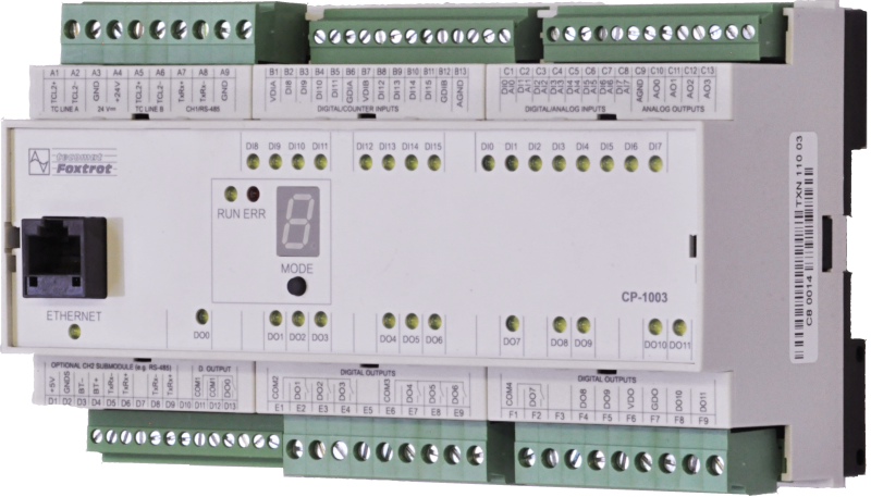
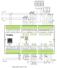
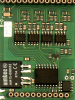
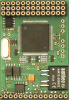
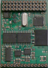
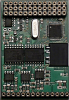
CP-1003TXN 110 03
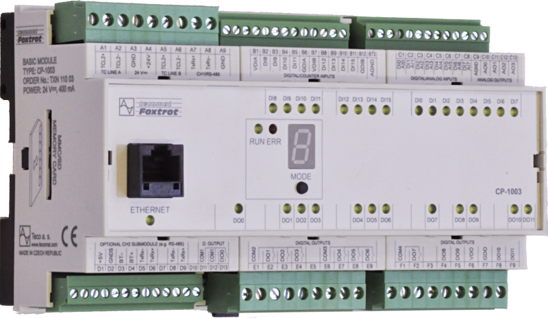
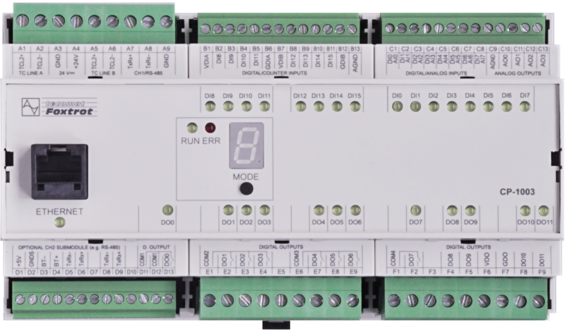
CP-1003, CPU, ETH100/10, 1x RS485, 1x SCH, 8xAI/DI, 8DI/HSC, 4xAO, 8xRO, 4xDO, 2xTCL2
| DI | 8x DI/HSC |
|---|---|
| DI/AI | 8x DI/AI |
| DO | |
| AI | |
| AO | 4x AO |
| COM | 1x ETH 10/100 1 × RS-485 1-3x Serial channel (1x free slot) 2 × TCL2 master |
| SENSOR |

The basic module CP-1003 is equipped with eight multi-purpose inputs, each of which can be used either as
The CP-1003 basic module is equipped with a central unit (CPU) of the L series, which is designed for applications with performance requirements.
It contains backed up CMOS RAM for user programs, data, tables, user registers and DataBox, Flash memory for user backup
program, slot for MMC / SD / SDHC memory card, real-time circuit, Ethernet interface, up to 4 serial channels (one with fixed RS-485 interface, another with slot
for the optional submodule) and two TCL2 system interfaces for connecting expansion modules that increase the number of I / O systems.
- analog (voltage, current or for passive temperature sensors) or as
- binary 24V, eight fast binary inputs with adjustable decision level
- four analog outputs ± 10 V,
- eight relay outputs and
- four fast transistor outputs with the possibility of direct connection of DC or stepper motors.
The CP-1003 basic module is equipped with a central unit (CPU) of the L series, which is designed for applications with performance requirements.
It contains backed up CMOS RAM for user programs, data, tables, user registers and DataBox, Flash memory for user backup
program, slot for MMC / SD / SDHC memory card, real-time circuit, Ethernet interface, up to 4 serial channels (one with fixed RS-485 interface, another with slot
for the optional submodule) and two TCL2 system interfaces for connecting expansion modules that increase the number of I / O systems.
| Order num. | TXN 110 03 |
|---|---|
| Teco code | TXN 110 03 |
| Categories | Foxtrot 1 - Basic modules |
| Tags | Sales and production discontinued |
| System parameters of the central unit | |
|---|---|
| Row of central unit | L |
| User program memory | 384 + 64 kB |
| Memory for user variables / including RETAIN variables | 192 kB/48 kB |
| Instruction length | 2 ÷ 10 bytes |
| Backup of program source code in PLC | Yes, in program backup memory (EEPROM) |
| On-line program change in PLC | Yes, including I / O configuration change |
| Memory for project archiving - internal | 2 MB |
| DataBox - additional internal data memory | 512 kB |
| Optional memory card slot | SD - Card Slot |
| Cycle time per 1k of logic instructions | 0,2 ms |
| Development environment | Mosaic |
| Programming languages | ST, IL, LD, FBD, SFC, CFC |
| RTC - Real time circuit | Yes |
| RAM and RTC backup 1) without / with backup battery | type. 500 hr / typ. 20,000 hours |
| Integrated Web server | Yes |
| Integrated Datalogger | Yes |
| Access to PLC variables via web API | Yes |
| Notice | 1) Applies to the basic module without power supply, the backup circuits are disconnected when the power supply is switched on 2) The serial interface CH1 is permanently equipped with an RS-485 interface. The serial interface type CH2 to CH4 is selectable via interchangeable submodules |
| COM - Communication - IP/Ethernet | |
| Ethernet 10/100 Mb (ETHx) | 1 |
| Available system modes on ETH and WLAN | UNI, PC, PLC, PLD |
| TCP / IP protocol | Yes |
| UDP protocol | Yes |
| HTTP protocol | Yes |
| Protocol MODBUS/TCP | Yes |
| SMTP protocol | Yes |
| IEC 60870-5-104 protocol | Yes |
| REST API | Yes |
| COM - Serial channels | |
| max. number of optional serial channels in the basic module | 4 |
| max. number of expanding serial channels on the TCL2 bus | 6 |
| Number of internal RS-232 serial channels | 1 |
| Available system modes on CH5-10 | UNI, CSJ (CAN) |
| Modbus RTU / ASCII master protocol | Yes |
| Modbus protocol RTU/ASCII slave | Yes |
| Profibus DP master protocol (<180 kbit/s) | Yes, on serial channels supporting PFB mode |
| COM - System buses | |
| TCL2 - system I/O bus | 2x TCL2 master |
| TCL2 - Range of one branch of the system I/O bus | 10 I / O modules + 4 operator panels + 6 serial channels |
| The communication rate of the system I / O bus | 345 kbps |
| System I / O bus terminating resistor | 120 Ω |
| DI - Parameters of binary inputs DC (group A) | |
| Parameters valid for inputs on the terminals | DI0÷DI7 |
| Number of inputs in group | 8 |
| Common wire | minus |
| Input type | Type 1 (IEC) |
| Galvanic isolation of inputs from internal/peripheral circuits | Yes, all external circuits connected to the module must meet the conditions for SELV circuits |
| Diagnostics | indication of energized input by LED on module panel |
| Input voltage for log. 0 | 0 V DC; -5 V DC min.; +5 V DC max. |
| Input voltage for log. 1 | 24 V DC; 15 V DC min.; 30 V DC max. |
| Input current at log. 1 (typ.) | 5 mA typ. |
| Delay from log. 0 to log. 1 | 500 μs |
| Delay from log. 1 to log. 0 | 500 μs |
| HSC - Special functions of binary inputs / counters | |
| Unidirectional counter (UP) | 2x (DI0); (DI2) |
| Two unidirectional counters (UP / UPB) | 2x (DI0/DI2); (DI2/DI3) |
| Bidirectional counter (UP/DOWN) | 2x (DI0/DI1); (DI2/DI3) |
| Counter with direction control (CLK/DIR) | 2x (DI0/DI1); (DI2/DI3) |
| Bi-directional counter with reset and intercept (UP / DOWN / CLR / CAP) | 1x (DI0/DI1/DI2/DI3) |
| Counter with direction control with reset and latch (CLK / DIR / CLR / CAP) | 1x (DI0/DI1/DI2/DI3) |
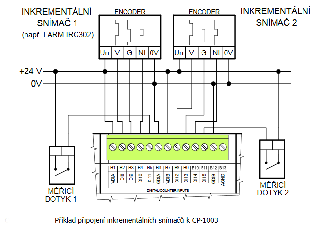
| IRC Basic (V/G) | 2x (DI0/DI1); (DI2/DI3) |
| IRC with Zero and Capture (V / G / NI / MD) | 1x (DI0/DI1/DI2/DI3) |
| Measure the pulse length | 4x (DI0,DI1, DI2, DI3) |
| Period measurement | 4x (DI0,DI1, DI2, DI3) |
| DO - Parameters of binary transistor outputs (group A) | |
| Number of transistor outputs | 4 |
| Number of output groups | 1 |
| Number of outputs in group | 4 |
| Output type | semiconductor output, half-bridge (push-pull) |
| Galvanic separation from internal circuits | Yes |
| Diagnostics | indication of energized output by LED on module panel |
| Switching voltage | 12 - 30 V DC |
| Output resistance | type. 0.3 Ω, max. 0.6 Ω |
| Switching time | typ. 1,6 μs |
| Opening time | typ. 0,6 μs |
| Short circuit protection | Yes |
| RO - Parameters of binary relay outputs (group A) | |
| Number of relay outputs | 7 |
| Number of output groups | 3 |
| Output type | electromechanical relay, unprotected output |
| Contact type | NO - Normally Open |
| Diagnose | Alarm signaling on panel module |
| Switching current | 2 A max., 100 mA min. |
| Switching voltage | 250 V AC max., 5 V AC min., 30V DC max. |
| Short-term output overload - inrush | 4 A max. |
| Short-circuit protection | No |
| AI - Organization of analog inputs | |
| Total number of analog inputs | 8 |
| Number of inputs per group | 8 |
| Number of analog input groups | 1 |
| Organization of analog inputs into groups | 8x AI (AI0÷AI7) |
| Input type | With common clamp |
| Common wire | Minus |
| Galvanic separation from internal circuits | Yes, 8 inputs together |
| Diagnostics | overload signaling in status word |
| Type of protection | integrated overvoltage protections |
| External power supply | No |
| Digital resolution | 12 bit |
| Converter type | Approximation |
| conversion time | 20 μs |
| AI - Analog Input Ranges (Group A) | |
| Parameters valid for inputs on the terminals | AI0÷AI7 |
| Voltage | 0 to 10 V / 2,726 mV |
| Voltage | 0 to 5 V / 2,726 mV |
| Voltage | 0 to 2 V / 610.4 μV |
| Voltage | 0 to 1 V / 610.4 μV |
| Voltage | 0 to 0.5 V / 610.4 μV |
| Input impedance in the voltage signal range | > 20 kΩ |
| Voltage input error - max. error at 25 ° C | ± 0.3% of full scale |
| Voltage input error - temperature coefficient | ± 0.02% of full scale / K |
| Voltage input error - non-linearity | ± 0.08% of full scale |
| Voltage input error - repeatability under steady state conditions | 0.05% of full scale |
| Permissible continuous overload - voltage input | -20 V to +30 V |
| Ccurrent | 0 - 20 mA |
| Current | 4-20 mA |
| Current - resolution 1 LSB | 6 μA |
| Input impedance in the current signal range | 100 Ω |
| Permissible continuous overload - current input, resistance 100 R | ± 5 V / 50 mA max |
| Open input detection | No |
| Passive sensor | Pt1000, W100 = 1,385 (-90 to +400 °C) |
| Passive sensor | Pt1000, W100 = 1,391 (-90 to +400 °C) |
| Passive sensor | Ni1000, W100 = 1,500 (–60 to +200 ° C) |
| Passive sensor | Ni1000, W100 = 1.617 (-60 to +200 ° C) |
| Passive sensor | Resistance transmitter 0-1 kOhm |
| Passive sensor | Resistance transmitter 0-2 kOhm |
| Passive sensor | Resistance transmitter 0-200 kOhm |
| Passive sensor | NTC Thermistor 12k / 25 °C (-40 to + 125 °C) |
| Resistance measurement error - maximum error at 25 ° C | ± 0.5% of full scale |
| AO - Analog output parameters | |
| Number of outputs in group | 4 |
| Common wire of group | minus |
| Galvanic isolation from internal circuits | Yes, along with the entrances |
| Output type | active voltage output |
| Converter resolution | 12 bit |
| Power supply | |
| Nominal supply voltage (V) | 24 V DC |
| Supply voltage, tolerances | 24 V DC, +25%, -15%, SELV |
| Supply voltage when backing up with an external battery | 27 V DC, +10%, –15%, SELV |
| Typical power input | 8 W |
| Maximum power input | 10 W |
| Module thermal/power loss | 10 W |
| Maximum current consumption (mA) | 500 mA |
| Galvanic separation of power supply from internal circuits | Yes |
| Internal protection | Yes, PTC reversible fuse |
| Size and weight | |
| Weight approx. | 300 g |
| Module width in multiples of M (17.5 mm) | 9M |
| Product dimensions (width x height x depth) | 158 x 90 x 62 mm |
| Operating conditions, product standards | |
| Product standard | ČSN EN 61131-2:2008 (idt IEC 61131-2:2007) - Programmable control units |
| Protection class of electrical object | II, according to ČSN EN 61140 ed.3: 2016 (idt IEC 61140:2016) |
| IP rating (Ingress Protection) according to ČSN EN 60529: 1993 (idt IEC 529: 1989) | IP20 |
| Operating areas | Normal according to ČSN 33 2000-1: 2003 (IEC 364-1: 1992 mod) |
| Degree of pollution | 1, according to ČSN EN 60664-1 ed.2:2008 ( idt IEC 60664-1:2007) |
| Overvoltage category installation | II, according to EN 60664-1 ed_2: 2008 (idt IEC 60641-1: 2007) |
| Type of device | Module on DIN rail |
| Working position | Vertical |
| Type of operation (operating frequency) | Continuous |
| Ambient operating temperatures | -20 °C to + 55 °C |
| Operating relative humidity | from 10 % up to 95 % without condensation |
| Operating atmospheric pressure | min. 70 kPa (<3,000 m above sea level) |
| Storage temperatures | –25 °C to +70 °C |
| Electromagnetic compatibility, Mechanical endurance | |
| Electromagnetic compatibility / Emission | A, according to EN 55032 ed. 2: 2017 (idt CISPR 32: 2015) |
| Emmisions - note | In premises where the use of radio and television receivers can be expected to be used a distance of 10 m from these devices may cause radio interference. In such a case, the user may be required to take appropriate action. |
| Electromagnetic compatibility / Immunity | min. as required by EN 61131-2: 2007 |
| Sinusoidal vibration endurance | 10 Hz to 57 Hz, amplitude 0,075 mm, 57 Hz to 150 Hz, acceleration 1 G (Fc test according to EN 60068-2-6: 1997 (idt IEC 68-2-6: 1995), 10 cycles per axis.) |
| Packaginng, transportation, storage | |
| Description | The module is packed in a paper box. This documentation is also part of the package. The outer packaging is carried out according to the scope of the order and the method of transport in a transport package provided with labels and other data necessary for transport. The product must not be exposed to direct weather conditions during transport and storage. Malting of the product is only allowed in clean rooms without conductive dust, aggressive gases and vapors. The most suitable storage temperature is 20 ° C |
| Installation | |
| Assembly description | Switchboard mounting |
| Module operation | |
| Commissioning | The module is operated, set and diagnosed from the MOSAIC programming environment or other parameterization software. The module is ready for operation after connecting the supply voltage and the CIB bus. The HW address is indicated on the label on the module. |
| Module diagnostics | The basic diagnostic system of the module is a part of its standard software. It operates from module power on and operates independently of the user. Diagnostic error states of the module and connected peripheral modules of the assembly are signaled |
| Maintenance | |
| Description | The module does not require any maintenance under general installation conditions. The operations in which a part of the module has to be dismantled must always be carried out with the supply voltage disconnected. |
| Notice | Because the module contains semiconductor components, it is necessary to follow the principles for working with electrostatic sensitive components when handling the removed cover. It is not allowed to directly touch the printed circuit boards without protective measures !!! |
| Warranty | |
| Generally | Warranty and complaint conditions are governed by the Terms and Conditions of Teco a.s. |
| Notice | You must meet all the conditions of this documentation before turning on the system. The system must not be put into service unless it has been verified and confirmed that the machinery meets the requirements of Directive 89/392 / EEC, in so far as it applies to it. Documentation subject to change. |
HW documentation
CP-1003 Basic documentation
1.04 MB, (CS, EN)
User manuals
Foxtrot1 - User's Guide, cze, , TXV00410_01
3.40 MB
Foxtrot1 - User Manual (en), TXV00410_02
4.30 MB
Files for designers
CP-1003 technical drawing DWG
168.04 kB
CP-1003 technical drawing DXF
492.66 kB
MR-0124
TXN 101 24
MR-0124, RS-422, with its own power supply and auto-identification, galvanic isolation
MR-0160
TXN 101 60
MR-0160, 2x CAN (SJA1000, Philips), with its own power supply, galvanic isolation
MR-0105
TXN 101 05
MR-0105, 1x RS-485, 2x RS-232 (FOXTROT only), GO with its own power supply and auto-identification
MR-0106
TXN 101 06
MR-0106, 2x RS-485, 1x RS-232 (FOXTROT only), with its own power supply and auto-identification, galvanic isolation
MR-0115
TXN 101 15
MR-0115, 3x RS-485, (FOXTROT only), with its own power supply and auto-identification, galvanic isolation

MR-0161
TXN 101 61
MR-0161, 1x CAN (SJA1000, Philips), with its own power supply, galvanic isolation
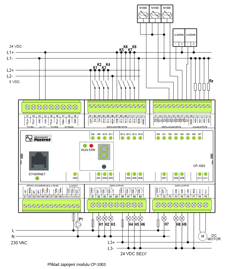
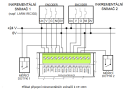
- MR-0105, MR-0106, MR-0115, fitted with CP-1000, CP-1001, CP-1003, CP-1091 - ...RxD2 RxD2 TxRx2+ Notes: In the CP-1003 - using the DO0 outlet - the D10 terminal must remain free in order to provide safe galvanic isolation of DO0 power o...
- CP-1003 - The CP-1003 basic module features eight multi-purpose inputs, each of which can be used either as an analogue input (voltage, current or a passive temperature sensor) or a binary 24 V input, with eight fast binary inputs featuring adjustable decisi...
- CH1 communication interface of the CP-1003 and CP-1091, RS485 basic modules - The serial interface of the basic CH1 module CP-1003 and CP-1091 is firmly fitted with the RS-485 interface without galvanic isolation (i.e. the interface signals have galvanic connection with the module power supply, with the CIB interface, th...
- Power dissipation of modules for calculation of switchboard heating - ...SCH, 4xAI/DI, 2xDI/230VAC, 2xRO, 2xCIB, 384/192kB CP-1001 6,0 W TXN 110 03 CP-1003, CPU, ETH100/10, 1x RS485, 1x SCH, 8xAI/DI, 8DI/HSC, 4xAO, 8xRO, 4xDO, 2xTCL2 CP-1003 10,0 W...
- TCL2 bus – the principles of design and installation - ...Maximum number of modules per bus TCL2 (TCL2A) Maximum number of modules per bus TCL2B (only for CP-1003) Peripheral modules IB, OS, IR, IT, OT, UC 10...
- Internal CIB master at the CP-10xx - The CP-10xx Foxtrot basic modules are as a standard fitted with an internal master of CIB (except for CP-1003). Depending on the type of basic module there are several options of power supply to the CIB with an internal master: The basic module...
- MR-0161 - CAN interface, with galvanic isolation - ...CP-10x4 CP-10x5 CP-10x6 CP-10x8 CP-1000 CP-1003 CP-1091 Signal Type of signal...
- MR-0114 - RS-485 interface, with galvanic isolation - ...CP-10x4 CP-10x5 CP-10x6 CP-10x8 CP-1000 CP-1003 CP-1091 Signal Type of signal Usage...
- MR-0104 - the RS-232 interface, with galvanic isolation - ...CP-10x4 CP-10x5 CP-10x6 CP-10x8 CP-1000 CP-1003 CP-1091 Signal Type of signal Usage...
- Communication interface CH2, using optional submodules - ...nce with the basic module type: Fig. 1 for the basic modules CP-1000 -1001 and CP-1091 Fig. 2 for the basic module CP-1003 Fig. 3 for the basic modules CP-10x4, CP-10x5. Fig. 4 for the basic modules CP-10x6, CP-10x8. ...
- Communication interface CH1 of the basic modules CP-10xx, RS-232 - The serial interface of the basic CH1 module of basic modules (except for the CP-1003) is firmly fitted with the RS-232 interface without galvanic isolation (i.e. the interface signals have galvanic connection with the module power supply by the CI...
- Foxtrot basic module power supply - ...also with DI/AI inputs on the basic module (typically connectors on the top side of the module); this does not apply to the CP-1003 - see Chapter 2.7.2 . These circuits are also galvanically connected with the power supply of the system, if the CH2...
- First generation Tecomat Foxtrot PLC - ..., Provedení: DIN-RAIL, Interface: Multi, Bus: TC700, Input: true, Output: true, Analog: true, Binary: true ] CP-1003 CP-1003-Základní modul Foxtrot [ AO: 4, DI: 8, DO: 12, Typ: PLC-Foxtrot, Výrobce: Teco, Provedení: DIN-RAIL,...
- DMX device control, connection to the CH4 interface of the CP-1000 module - The following example describes the connection of the DMX bus to the CH4 communication interface of the CP-1000 . basic module. In this way it is possible to control up to 512 devices on the DMX bus from the user program of the Foxtrot system. Supp...
No data available.