


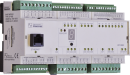
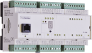
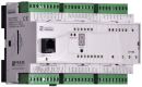
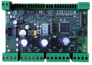
MR-0161TXN 101 61
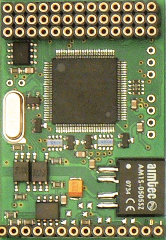
MR-0161, 1x CAN (SJA1000, Philips), with its own power supply, galvanic isolation
| DI | |
|---|---|
| DI/AI | |
| DO | |
| AI | |
| AO | |
| COM | 2x CAN |
| SENSOR |
| Picture | Variant | Variant description |
|---|---|---|

|
MR-0161 |
MR-0161, 1x CAN (SJA1000, Philips), with its own power supply, galvanic isolation
| Order num. | TXN 101 61 |
|---|---|
| Teco code | TXN 101 61 |
| Categories | Foxtrot 1 - Accessories for basic modules, TC700 - Accessories for central modules |
| Tags | Sales and production discontinued |
| COM - Serial channels | |
|---|---|
| Max. baud rate | 500/250 kBd |
| Max. length of connected line (RS-485) | 100/250 m |
| Number of internal CAN ports | 1 |
| Power supply | |
| Supply voltage, tolerances | The submodule is powered from the power supply the terminal device in which it is installed. |
| Maximum power input | 1,2 W |
| Galvanic separation of power supply from internal circuits | No |
| Insulation voltage of galvanic separation | 1 000 VDC |
| Size and weight | |
| Weight approx. | 25 g |
| Product dimensions (width x height x depth) | 35,6 x 52 x 10 mm |
| Operating conditions, product standards | |
| Product standard | ČSN EN 61131-2:2008 (idt IEC 61131-2:2007) - Programmable control units |
| Protection class of electrical object | III, according to ČSN EN 61140 ed.3: 2016 (idt IEC 61140:2016) |
| Degree of pollution | 2, according to ČSN EN 60664-1 ed.2: 2008 (idt IEC 60664-1: 2007) |
| Overvoltage category installation | II, according to EN 60664-1 ed_2: 2008 (idt IEC 60641-1: 2007) |
| Type of device | Module on DIN rail |
| Type of operation (operating frequency) | Continuous |
| Ambient operating temperatures | -20 °C to + 55 °C |
| Operating relative humidity | from 10 % up to 95 % without condensation |
| Operating atmospheric pressure | min. 70 kPa (<3,000 m above sea level) |
| Storage temperatures | –25 °C to +70 °C |
| Packaginng, transportation, storage | |
| Description | The submodule is packed in a paper box according to the internal packing instructions. This documentation is also part of the package. The outer packaging is carried out according to the scope of the order and the method of transport in a transport package provided with transport labels and other data necessary for transport. Transport from the manufacturer is carried out in the manner agreed upon when ordering. The transport of the product by the customer's own means must be carried out by covered means of transport, in the position specified by the label on the packaging. The box must be stored in such a way that it does not move spontaneously and the outer packaging is not damaged. The product must not be exposed to direct weather conditions during transport and storage. Transport is permitted at temperatures of -40 ° C to 70 ° C, relative humidity of 10% to 95% (non-condensing) and a minimum atmospheric pressure higher than 70 kPa. The product may only be stored in clean rooms free of conductive dust, aggressive gases and vapors. The most suitable storage temperature is 20 ° C. |
| Installation | |
| Assembly description | The installation of the submodule into the TEMPO system is performed according to the relevant documentation. The submodule is installed in positions accessible after loosening the two screws and sliding out and opening the back cover. The submodule must be equipped with the full number of tips (the number of terminals on the submodule and the motherboard must match). |
| Exchangeable submodules | Submodules contain components that are sensitive to electrostatic charge, so follow the guidelines for working with these circuits! Manipulate only on the submodule removed from the frame! When replacing the submodules, the correctness of the placement of the submodule cavities against the tips on the motherboard must be carefully checked. The sockets do not have position coding and in case of incorrect installation, the submodule or even the motherboard may be damaged when the power supply is switched on again !!! |
| Connection | |
| Connection description |
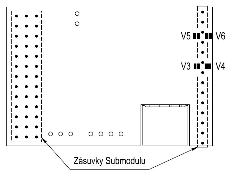
577 / 5000 Výsledky překladu The terminating impedance of the interface can also be connected by flying the solder jumpers on the printed circuit board. The jumpers are located near the terminals of a single-row socket (on the opposite side of the board to the socket). V3, V4 - jumpers for connection of terminating impedance of interface 1 V5, V6 - jumpers for connection of termination impedance of interface 2 For Submodule MR-0161, connect only V3 and V4. Detailed connection data, principles of correct installation, examples of interface connections and principles of increasing durability and reliability are given in the TXV 001 08.01 design manual. |
| Module operation | |
| Module configuration | The module is operated, set up and diagnosed from the Mosaic development environment. |
| Commissioning | The module is ready for operation after connecting the supply voltage. The MODE button is available on the module panel to display the currently set Ethernet IP address. The parameters of all interfaces are set in the Mosaic development environment. |
| Warranty | |
| Generally | Warranty and complaint conditions are governed by the Terms and Conditions of Teco a.s. |
| Notice | You must meet all the conditions of this documentation before turning on the system. The system must not be put into service unless it has been verified and confirmed that the machinery meets the requirements of Directive 89/392 / EEC, in so far as it applies to it. Documentation subject to change. |
HW documentation
MR-0160/161 - Basic documentation
154.75 kB, (CS, EN)
User manuals
OVERVIEW OF TECOMAT SUB-MODULES (en)
671.90 kB, (EN)
CP-1003
TXN 110 03
CP-1003, CPU, ETH100/10, 1x RS485, 1x SCH, 8xAI/DI, 8DI/HSC, 4xAO, 8xRO, 4xDO, 2xTCL2
CP-1008
TXN 110 08
CP-1008, CPU, ETH100/10, 1xRS232, 1xSCH, 10xAI/DI, 2xAI, 4xAO, 7xRO, 4xSSR, 1xCIB
CP-1091
TXN 110 91
CP-1091, CPU, ETH100/10, 1x RS232, 1xSCH, 6xAI/DI, 6xDI, 1x DI/230VAC; 9xDO; 3xRO; 4xAO 1xCIB
CP-1972
TXN 119 72
CP-1972, CPU, ETH100/10, 1xRS485, 1xSCH, 4xDI, 2xAI/DI, 2xAO/10V, 3xDO PWM/3A, 8xDO/1A 3xDO/3A, 1xCIB, 1x TCL2
CP-7004
TXN 170 04
CP-7004, CPU, Ethernet 10/100Mbit RJ-45, 192kB+64kB, 0.5 DataBox, expandable +3MB, 2x SCH, USB, MMC/SD slot
CP-7007
TXN 170 07
CP-7007, CPU, 320kB+192kB, DataBox 0.5MB, expandable +3MB, 2x SCH, 1xUSB, 1xEthernet 10/100Mbit, MMC/SD slot
- MR-0161 - CAN interface, with galvanic isolation - The MR-0161 submodule allows the connection of PLC TECOMAT Foxtrot to CAN network with data transfer rates of 500, 250, 125, 50, 20 or 10 kBd. It can only be used in the CAN, CAS and CAB modes (further see TXV 004 03 ). Table. 1&nb...
No data available.