

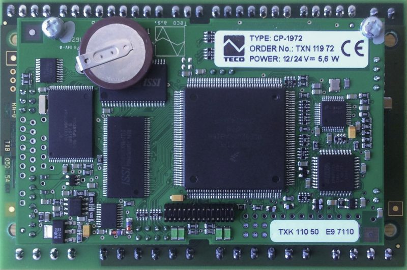
CP-1972TXN 119 72
CP-1972, CPU, ETH100/10, 1xRS485, 1xSCH, 4xDI, 2xAI/DI, 2xAO/10V, 3xDO PWM/3A, 8xDO/1A 3xDO/3A, 1xCIB, 1x TCL2
| DI | 4x DI |
|---|---|
| DI/AI | |
| DO | |
| AI | 2x AI |
| AO | |
| COM | 1x ETH 10/100 1x RS-485 3x Serial channel (1x free slot) 1x TCL2 master 1x CIB masterA |
| SENSOR |
| Picture | Variant | Variant description |
|---|---|---|

|
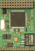
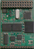
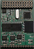
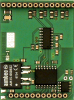
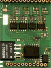
CP-1972 |
CP-1972 is a first-generation Foxtrot central module in a customer (OEM) design without its own cover. The modules are equipped with a central unit (CPU) of the L series, which is designed for applications with performance requirements. It includes backed up CMOS RAM for user programs, data, tables, user registers and DataBox, Flash memory for user program backup, MMC / SD / SDHC memory card slot and real time circuit.
| Order num. | TXN 119 72 |
|---|---|
| Teco code | TXN 119 72 |
| Categories | Foxtrot 1 - OEM basic modules |
| Tags | Sales and production discontinued |
| System parameters of the central unit | |
|---|---|
| Row of central unit | L |
| User program memory | 384 + 64 kB |
| Memory for user variables / including RETAIN variables | 192 kB/48 kB |
| Instruction length | 2 ÷ 10 bytes |
| Backup of program source code in PLC | Yes, in program backup memory (EEPROM) |
| On-line program change in PLC | Yes, including I / O configuration change |
| Memory for project archiving - internal | 2 MB |
| DataBox - additional internal data memory | 512 kB |
| Optional memory card slot | SD - Card Slot |
| Cycle time per 1k of logic instructions | 0,2 ms |
| Development environment | Mosaic v2018.2 or higher |
| Programming languages | ST, IL, LD, FBD, SFC, CFC |
| RTC - Real time circuit | No |
| RAM and RTC backup 1) without / with backup battery | type. 500 hr / typ. 20,000 hours |
| Integrated Web server | Yes |
| Integrated Datalogger | Yes |
| Access to PLC variables via web API | Yes |
| Notice | 1) Applies to the basic module without power supply, the backup circuits are disconnected when the power supply is switched on 2) The serial interface CH1 is permanently equipped with an RS-485 interface. The serial interface type CH2 to CH4 is selectable via interchangeable submodules |
| COM - Communication - IP/Ethernet | |
| Ethernet 10/100 Mb (ETHx) | 1 |
| Available system modes on ETH and WLAN | UNI, PC, PLC, PLD |
| TCP / IP protocol | Yes |
| UDP protocol | No |
| HTTPS protocol | No |
| HTTP protocol | No |
| WebSocket protocol | No |
| Protocol MODBUS/TCP | No |
| SMTP protocol | No |
| IEC 60870-5-104 protocol | No |
| REST API | No |
| COM - Serial channels | |
| max. number of optional serial channels in the basic module | 3 |
| max. number of expanding serial channels on the TCL2 bus | 6 |
| Number of internal RS-485 serial channels | 1 |
| Communication speed of the internal serial channel | optional |
| Available system modes on CH5-10 | UNI, CSJ (CAN) |
| Modbus RTU / ASCII master protocol | No |
| Modbus protocol RTU/ASCII slave | No |
| Profibus DP master protocol (<180 kbit/s) | No |
| COM - System buses | |
| TCL2 - system I/O bus | 1x TCL2 master |
| TCL2 - Range of one branch of the system I/O bus | 10 I / O modules + 4 operator panels + 6 serial channels |
| The communication rate of the system I / O bus | 345 kbps |
| System I / O bus terminating resistor | 120 Ω |
| CIB - Common Installation Bus (R): Installation I/O bus | 1x CIB master (100 mA) |
| CIB - Address range of one branch of the installation bus | 32 CFox I/O modules |
| DI - Parameters of binary inputs DC (group A) | |
| Number of inputs in group | 4 |
| Galvanic isolation of inputs from internal/peripheral circuits | No |
| Max. measuring voltage on the connected contact | 7 V DC |
| Max. contact current | 2 mA |
| Max. resistance for closed contact, log. 1 | < 1 kΩ |
| Min. resistance for open contact, log. 0 | > 2 kΩ |
| Frequency of measurement | PLC cycle |
| DO - Parameters of binary transistor outputs (group A) | |
| Number of transistor outputs | 8 |
| Number of output groups | 2 |
| Number of outputs in group | 4 |
| Organization of transistor outputs into groups | 4x (DO0-DO3) + 4x (DO4-DO7) |
| Output type | semiconductor output, half-bridge (push-pull) |
| Galvanic separation from internal circuits | No |
| Switching voltage | 10 – 32 V DC |
| Switching current, output load | 2.7 A each output permanently, pulse 4 A |
| Output resistance | type. 0.3 Ω, max. 0.6 Ω |
| DO - Parameters of binary transistor outputs (group B) | |
| Parameters valid for the terminals | LED0 - LED2 |
| Number of transistor outputs | 3 |
| Number of output groups | 1 |
| Common group conductor | minus |
| Output type | NMOS transistor with open collector. (Power load) |
| Galvanic separation from internal circuits | No |
| Switching voltage | 40 V DC max. |
| Switching current, output load | 3 A max. |
| Switching time | typ. 25 μs |
| Opening time | typ. 25 μs |
| Internal protection | Temperature protection, current limitation |
| Short-circuit current | typ. 5 A |
| DO - Parameters of binary transistor outputs (group C) | |
| Number of transistor outputs | 2 |
| Number of output groups | 1 |
| Organization of transistor outputs into groups | 2x (DO8-DO9) |
| Common group conductor | minus |
| Output type | Open-collector PMOS transistor. (Load on GND) |
| Galvanic separation from internal circuits | No |
| Switching voltage | 6 - 36 V DC |
| Switching current, output load | each output permanently 3.7 A |
| Output resistance | typ. 90 mΩ |
| Switching time | typ. 30 μs |
| Opening time | typ. 500 μs |
| Internal protection | Temperature protection, current limitation |
| Residual current | max. 5 μA |
| AI - Organization of analog inputs | |
| Total number of analog inputs | 2 |
| Input type | Current input |
| Common wire | Minus |
| Galvanic separation from internal circuits | No |
| Diagnostics | overload signaling in status word |
| Digital resolution | 12 bit |
| Converter type | Approximation |
| conversion time | 20 μs |
| Repeat time of sample | 80 μs typ. |
| Filtration | comb filter, 32 samples |
| AI - Analog Input Ranges (Group A) | |
| Ccurrent | 0 to 20 mA / 0.3906 μA |
| Input impedance in the current signal range | 100 Ω |
| Current input error - maximum error at 25 ° C | ±0.3% of full scale |
| Error current input - temperature coefficient | ± 0.02% of full scale / K |
| Error current input - nonlinearity | ± 0.08% of full scale |
| Error current input - repeatability at steady-state conditions | 0.05% of full scale |
| Output for supplying measuring current loops | |
| Output voltage | 24 V ± 10% |
| Output current | 45 mA |
| Endurance against short circuit | No |
| Short circuit protection | No |
| AO - Analog output parameters | |
| Common wire of group | minus |
| Converter resolution | 12 bit |
| Analog output error - maximum error at 25 ° C | ± 0.2% of full scale |
| Analog output error - temperature coefficient | ± 0.3% of full scale / K |
| Analog output error - linearity | ± 0.7% of full scale |
| Analog output error - repeatability under steady state conditions | ± 0.5% of full scale |
| Voltage output - voltage | 0 - 10,5 V |
| Voltage output - Resolution 1 LSB | 2,589 mV |
| Voltage output - maximum output current | 10 mA |
| Power supply | |
| Nominal supply voltage (V) | 12 V DC |
| Supply voltage, tolerances | 12/24 V DC, +25%, -15%, SELV |
| Maximum power input | 5 W |
| Maximum current consumption (mA) | 300 mA |
| Description of power supply | The difference between the typical and the maximum power is given by the possible load on the CIB buses |
| CIB branch power supply - parameters of the built-in master | 1x 100 mA/ 24 V DC |
| Size and weight | |
| Weight approx. | 200 g |
| Product dimensions (width x height x depth) | 120 x 80 x 50 mm |
| Product dimensions (width x height x depth) | 120 x 80 x 50 mm |
| Operating conditions, product standards | |
| Product standard | ČSN EN 61131-2:2008 (idt IEC 61131-2:2007) - Programmable control units |
| Protection class of electrical object | II, according to ČSN EN 61140 ed.3: 2016 (idt IEC 61140:2016) |
| IP rating (Ingress Protection) according to ČSN EN 60529: 1993 (idt IEC 529: 1989) | IP00 |
| Operating areas | Normal, acc. ČSN 33 2000-1 ed.2: 2009 (mod IEC 60354-1:2005) |
| Degree of pollution | 1, according to ČSN EN 60664-1 ed.2:2008 ( idt IEC 60664-1:2007) |
| Overvoltage category installation | II, according to EN 60664-1 ed_2: 2008 (idt IEC 60641-1: 2007) |
| Type of device | For spacers |
| Working position | Vertical |
| Type of operation (operating frequency) | Continuous |
| Ambient operating temperatures | -20 °C to + 55 °C |
| Operating relative humidity | from 10 % up to 95 % without condensation |
| Operating atmospheric pressure | min. 70 kPa (<3,000 m above sea level) |
| Storage temperatures | –25 °C to +70 °C |
| Electromagnetic compatibility, Mechanical endurance | |
| Electromagnetic compatibility / Emission | B, according to EN 55032 ed. 2: 2017 (idt CISPR 32: 2015) |
| Emmisions - note | In premises where the use of radio and television receivers can be expected to be used a distance of 10 m from these devices may cause radio interference. In such a case, the user may be required to take appropriate action. |
| Electromagnetic compatibility / Immunity | min. as required by EN 61131-2: 2007 |
| Sinusoidal vibration endurance | 10 Hz to 57 Hz, amplitude 0,075 mm, 57 Hz to 150 Hz, acceleration 1 G (Fc test according to EN 60068-2-6: 1997 (idt IEC 68-2-6: 1995), 10 cycles per axis.) |
HW documentation
CP-1972 - Basic documentation
154.64 kB
CP-1972 - programming
2.76 MB
EC - Declaration of Conformity
Foxtrot - EC Declaration of conformity
295.20 kB, (EN, RU, DE, UA)
MR-0160
TXN 101 60
MR-0160, 2x CAN (SJA1000, Philips), with its own power supply, galvanic isolation

MR-0161
TXN 101 61
MR-0161, 1x CAN (SJA1000, Philips), with its own power supply, galvanic isolation
MR-0105
TXN 101 05
MR-0105, 1x RS-485, 2x RS-232 (FOXTROT only), GO with its own power supply and auto-identification
MR-0106
TXN 101 06
MR-0106, 2x RS-485, 1x RS-232 (FOXTROT only), with its own power supply and auto-identification, galvanic isolation
MR-0115
TXN 101 15
MR-0115, 3x RS-485, (FOXTROT only), with its own power supply and auto-identification, galvanic isolation
MR-0124
TXN 101 24
MR-0124, RS-422, with its own power supply and auto-identification, galvanic isolation


- Foxtrot OEM control systems and OEM peripheral modules - The Foxtrot 2 series offers several variants of basic modules in an "open-frame" design, along with corresponding peripheral modules. These modules are designed to accommodate customer-defined input and output parameters, with a selection of measure...
No data available.