

MR-0114TXN 101 14
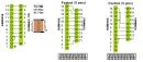
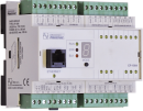
MR-0114, RS-485 galvanic isolation, self-source and auto-identification
| DI | |
|---|---|
| DI/AI | |
| DO | |
| AI | |
| AO | |
| COM | 1x RS-485 |
| SENSOR |
| Picture | Variant | Variant description |
|---|---|---|

|
MR-0114 |
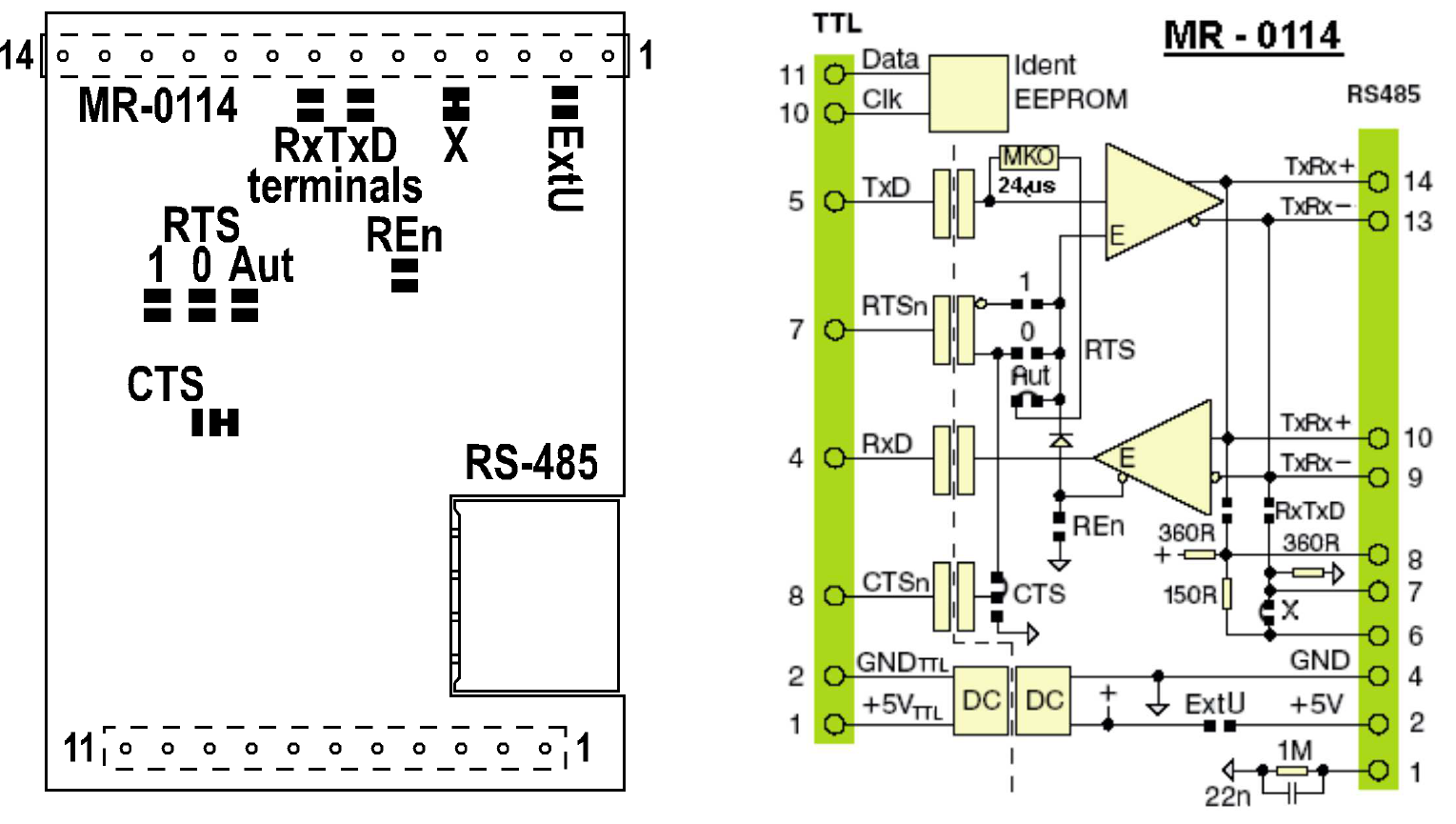
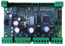
The MR-0114 submodule contains an RS-485 interface. The internal connection ensures galvanic separation of the interface from the system and power supply circuits. At the same time, the module contains identification circuits The user has the ability to identify the type of submodule used from the development environment.
| Order num. | TXN 101 14 |
|---|---|
| Teco code | TXN 101 14 |
| Categories | Foxtrot 1 - Accessories for basic modules, TC700 - Accessories for central modules |
| Tags | Sales and production discontinued |
| COM - Serial channels | |
|---|---|
| Number of internal RS-485 serial channels | 1 |
| Max. baud rate | 2 MBd |
| Note on max. Speed | If the RTS jumper is connected to AUTO, the maximum speed will be 200 kBd, otherwise 2 MBd. |
| Receiver sensitivity (RS-485) | min. ±200 mV |
| Signal output level (RS-485) | typ. 3,7 V |
| Max. length of connected line (RS-485) | 1200 m |
| Note on cable length | The maximum length applies to twisted and shielded cable and communication speed max. 120 kBd. |
| Power supply | |
| Supply voltage, tolerances | The submodule is powered from the power supply the terminal device in which it is installed. |
| Maximum power input | 1,2 W |
| Galvanic separation of power supply from internal circuits | No |
| Insulation voltage of galvanic separation | 1 000 VDC |
| Size and weight | |
| Weight approx. | 50 g |
| Product dimensions (width x height x depth) | 47 × 36 × 15 mm |
| Operating conditions, product standards | |
| Protection class of electrical object | III, according to ČSN EN 61140 ed.3: 2016 (idt IEC 61140:2016) |
| Operating areas | Normal, acc. ČSN 33 2000-1 ed.2: 2009 (mod IEC 60354-1:2005) |
| Degree of pollution | 2, according to ČSN EN 60664-1 ed.2: 2008 (idt IEC 60664-1: 2007) |
| Overvoltage category installation | II, according to EN 60664-1 ed_2: 2008 (idt IEC 60641-1: 2007) |
| Type of device | Submodule |
| Type of operation (operating frequency) | Continuous |
| Ambient operating temperatures | -20 °C to + 55 °C |
| Operating relative humidity | from 10 % up to 95 % without condensation |
| Operating atmospheric pressure | min. 70 kPa (<3,000 m above sea level) |
| Storage temperatures | –25 °C to +70 °C |
| Packaginng, transportation, storage | |
| Description | The submodule is packed in a paper box according to the internal packing instructions. This documentation is also part of the package. Outer packaging is carried out according to the scope of the order and the method of transport in a transport package provided with labels and other data necessary for transport. Transport from the manufacturer is carried out in the manner agreed upon when ordering. The transport of the product by the customer's own means must be carried out by covered means of transport in the position specified by the label on the packaging. The box must be stored in such a way that it does not move spontaneously and the outer packaging is not damaged. The product must not be exposed to direct weather conditions during transport and storage. The product may only be stored in clean rooms free of conductive dust, aggressive gases and vapors. The most suitable storage temperature is 20 ° C. |
| Installation | |
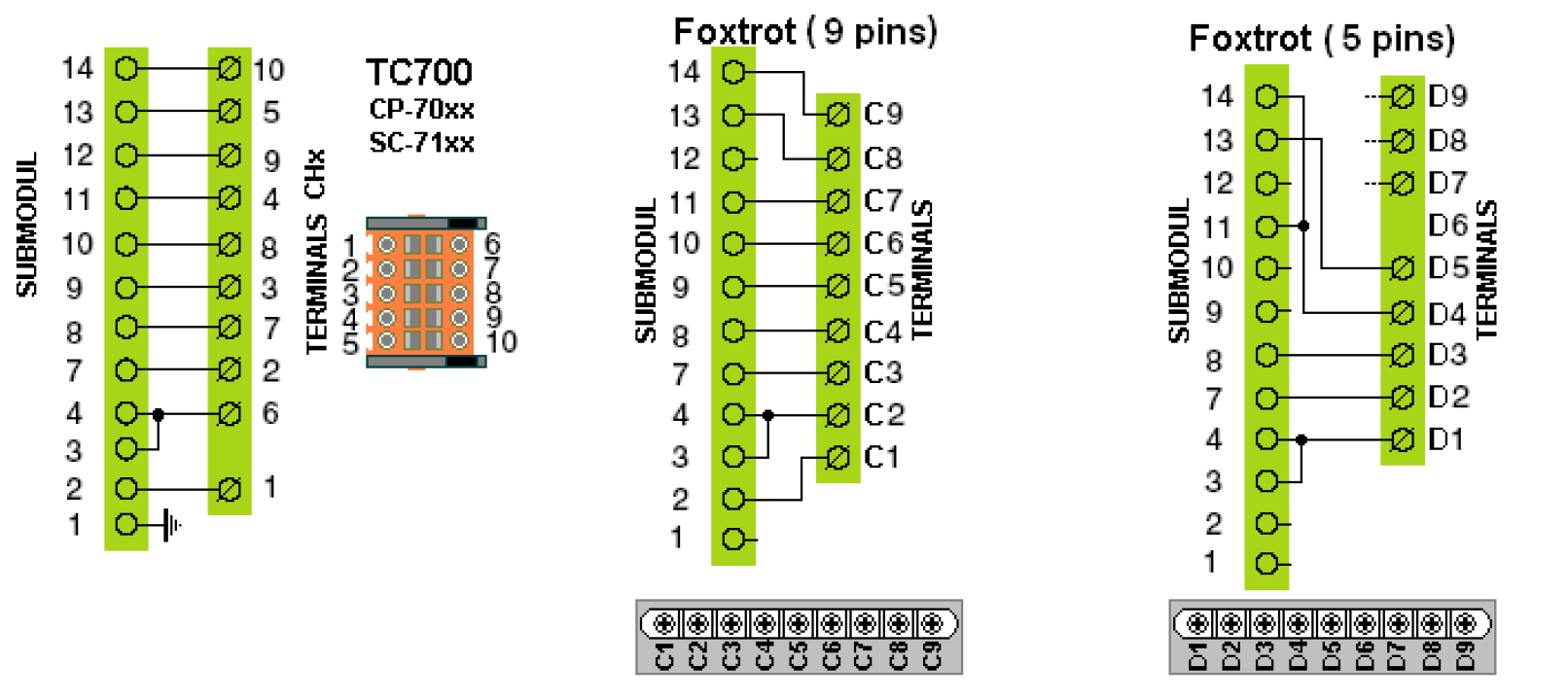
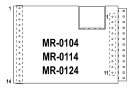
| Assembly description | The installation of the submodule in the terminal device is always described in the documentation of the respective device. The submodule is mounted on the tips of the connector forks in the terminal device so that the 14-socket socket of the submodule is exactly opposite the 14-pin connector plug and the 11-socket socket is mounted on those connector forks that come out for insertion. into the sockets: in the case of a connector with a single-row plug, these are all its tips; See Fig. 3.1. |
| Exchangeable submodules | When connecting and / or replacing submodules, the correctness of the fitting of the submodule cavities against the fork tips of the terminal connector must be carefully checked. The sockets do not have position coding and in case of incorrect installation, the submodule and / or the terminal device may be damaged when the power supply is switched on again !!! |
| Connection | |
| Serial channels | Socket strip |
| Module operation | |
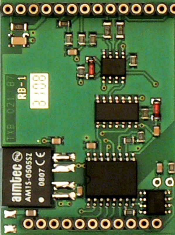
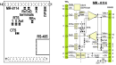
| Module configuration | The submodules have printed solder jumpers arranged on the printed circuit board, which can be used to modify the functions of some signals, or they can be used to connect the impedance termination of the communication line (if the submodule is at its end). Submodules are supplied with jumpers configured for the most commonly used submodule function. The figure illustrates the meaning, location and connection of individual jumpers. The configuration of some jumpers is realized already in the stage of production of the printed circuit board by a printed circuit board between the jumper surfaces. This applies to the jumpers marked 'X' and 'CTS' on MR-0114. For these jumpers, the ribbon cable must first be interrupted before changing their configuration. Then it is possible to connect the surfaces only with a drop of tin applied by soldering. The 'RTS Aut' jumper on the MR-0114 submodule is connected only by a drop of tin. The remaining jumpers are not connected. |
| Commissioning | The submodule is ready for operation after checking the connection of jumpers, correct insertion into the position in the terminal device and switching on the power supply of the system. |
| Module diagnostics | The submodule itself is not equipped with any diagnostics. The status of the communication line (activity of transmitted data, received data and RTS signal) is usually indicated by LED diodes on the terminal device. More detailed information can be found in the documentation of the respective device. |
| Maintenance | |
| Description | The module does not require any maintenance under general installation conditions. The operations in which a part of the module has to be dismantled must always be carried out with the supply voltage disconnected. |
| Warning | Because the submodule contains semiconductor components, it is necessary to follow the principles for working with electrostatic sensitive components when handling it. It is not allowed to directly touch the printed circuit boards without protective measures !!! |
| Warranty | |
| Generally | Warranty and complaint conditions are governed by the Terms and Conditions of Teco a.s. |
| Warning | All conditions of this documentation must be met before switching on the device. The system must not be put into service unless it has been verified and confirmed that the environment of which the module becomes a part meets the requirements of Directive 89/392 / EEC, if applicable. Documentation subject to change. |
HW documentation
MR-0104/114/124 - Basic documentation
424.01 kB, (CS, EN)
User manuals
OVERVIEW OF TECOMAT SUB-MODULES (en)
671.90 kB, (EN)
CP-1003
TXN 110 03
CP-1003, CPU, ETH100/10, 1x RS485, 1x SCH, 8xAI/DI, 8DI/HSC, 4xAO, 8xRO, 4xDO, 2xTCL2
CP-1008
TXN 110 08
CP-1008, CPU, ETH100/10, 1xRS232, 1xSCH, 10xAI/DI, 2xAI, 4xAO, 7xRO, 4xSSR, 1xCIB
CP-1091
TXN 110 91
CP-1091, CPU, ETH100/10, 1x RS232, 1xSCH, 6xAI/DI, 6xDI, 1x DI/230VAC; 9xDO; 3xRO; 4xAO 1xCIB
CP-1972
TXN 119 72
CP-1972, CPU, ETH100/10, 1xRS485, 1xSCH, 4xDI, 2xAI/DI, 2xAO/10V, 3xDO PWM/3A, 8xDO/1A 3xDO/3A, 1xCIB, 1x TCL2

CP-7004
TXN 170 04
CP-7004, CPU, Ethernet 10/100Mbit RJ-45, 192kB+64kB, 0.5 DataBox, expandable +3MB, 2x SCH, USB, MMC/SD slot
CP-7007
TXN 170 07
CP-7007, CPU, 320kB+192kB, DataBox 0.5MB, expandable +3MB, 2x SCH, 1xUSB, 1xEthernet 10/100Mbit, MMC/SD slot
- Connection of two Foxtrot systems using the RS-485 interface (the MR-0114 submodule) - ...elating to the RS-485. Fig. 1 The diagram of interconnection of two Foxtrot systems with the RS-485 interface (the MR-0114 submodule)....
- RS-485 interface (the MR-0114 submodule) of the CH2 communication interface, characteristics - The RS-485 serial interface submodule (the MR-0114 type, order no. TXN 101 14) is fitted with a complete circuit of bus termination, terminated at C4 (signal BT +) and C3 (signal BT) terminals, see Fig..1. The termination is connected to the bus by...
- MR-0114 - RS-485 interface, with galvanic isolation - The MR-0114 submodule provides the conversion of the serial interface TTL signals to the galvanically isolated RS-485 interface. This interface operates in a half-duplex mode, and makes multipoint (multidrop) linking of participants possible. Prope...
- Communication interface CH2 ÷ CH4, using multiple submodules - ...RS-232 RS-232 none none MR-0114 RS-232 RS-485 none none...
- Connecting the LG air conditioning units - ...Notes: The CH2 communication interface of the CP-1000 basic module in the example is fitted with the MR-0114 submodule; for more information see the documentation . The RS-485 interface connecting cable bet...
- Connecting the SAMSUNG air conditioning units - ...Notes: The CH2 communication interface of the CP-1000 basic module in the example is fitted with the MR-0114 submodule; for more information see the documentation. The RS-485 interface connecting cable between the...
- MR-0152 - PROFIBUS DP interface, with galvanic isolation - ...l interface corresponds with the RS-485 standard, the serial channel connection is the same as in the case of the submodule MR-0114 (see Table . 2 ), including the possibility of termination....
- DMX with MR-0114 submodule - Hi, Is it possible to use DMX512 with MR-0114 submodule? Regards, Zsolt