
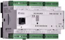
CP-1091TXN 110 91
CP-1091, CPU, ETH100/10, 1x RS232, 1xSCH, 6xAI/DI, 6xDI, 1x DI/230VAC; 9xDO; 3xRO; 4xAO 1xCIB
| DI | 6x DI/HSC 1x DI (230 V AC) |
|---|---|
| DI/AI | 6x DI/AI |
| DO | |
| AI | |
| AO | |
| COM | 1x ETH 1x RS-485 1x slot for Submodule 1x TCL2 master 1x CIB master |
| SENSOR |
| Picture | Variant | Variant description |
|---|---|---|

|
CP-1091 | |
|
|
CP-1091_kopie_93 |
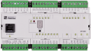
CP-1091, CPU, ETH100/10, 1x RS232, 1xSCH, 6xAI/DI, 6xDI, 1x DI/230VAC; 2xDI/230VAC,9xDO; 3xRO, 1xCIB
| Order num. | TXN 110 91 |
|---|---|
| Teco code | TXN 110 91 |
| Categories | Foxtrot 1 - Basic modules |
| Tags | Sales and production discontinued |
| System parameters of the central unit | |
|---|---|
| Row of central unit | L |
| User program memory | 384 + 64 kB |
| Memory for user variables / including RETAIN variables | 192 kB/48 kB |
| Instruction length | 2 ÷ 10 bytes |
| Backup of program source code in PLC | Yes, in program backup memory (EEPROM) |
| On-line program change in PLC | Yes, including I / O configuration change |
| Memory for project archiving - internal | 2 MB |
| DataBox - additional internal data memory | 512 kB |
| Optional memory card slot | SD - Card Slot |
| Cycle time per 1k of logic instructions | 0,2 ms |
| Development environment | Mosaic |
| Programming languages | ST, IL, LD, FBD, SFC, CFC |
| RTC - Real time circuit | No |
| RAM and RTC backup 1) without / with backup battery | type. 500 hr / typ. 20,000 hours |
| Integrated Web server | Yes |
| Integrated Datalogger | Yes |
| Access to PLC variables via web API | Yes |
| Notice | 1) Applies to the basic module without power supply, the backup circuits are disconnected when the power supply is switched on 2) The serial interface CH1 is permanently equipped with an RS-485 interface. The serial interface type CH2 to CH4 is selectable via interchangeable submodules |
| COM - Communication - IP/Ethernet | |
| Ethernet 10/100 Mb (ETHx) | 1 |
| Available system modes on ETH and WLAN | UNI, PC, PLC, PLD |
| TCP / IP protocol | Yes |
| UDP protocol | No |
| HTTP protocol | No |
| WebSocket protocol | No |
| Protocol MODBUS/TCP | No |
| SMTP protocol | No |
| IEC 60870-5-104 protocol | No |
| REST API | No |
| COM - Serial channels | |
| max. number of optional serial channels in the basic module | 2 |
| max. number of expanding serial channels on the TCL2 bus | 6 |
| Number of internal RS-485 serial channels | 1 |
| Communication speed of the internal serial channel | optional |
| Available system modes on CH5-10 | UNI, CSJ (CAN) |
| Modbus RTU / ASCII master protocol | No |
| Modbus protocol RTU/ASCII slave | No |
| Profibus DP master protocol (<180 kbit/s) | No |
| COM - System buses | |
| TCL2 - system I/O bus | 1x TCL2 master |
| TCL2 - Range of one branch of the system I/O bus | 10 I / O modules + 4 operator panels + 6 serial channels |
| The communication rate of the system I / O bus | 345 kbps |
| System I / O bus terminating resistor | 120 Ω |
| CIB - Common Installation Bus (R): Installation I/O bus | 1x CIB master (100 mA) |
| CIB - Address range of one branch of the installation bus | 32 CFox I/O modules |
| DI - Organization of binary inputs | |
| Total number of binary inputs | 13 |
| Number of groups of binary inputs | 3 |
| Organization of binary inputs into groups |
6x DI (DI0-DI5) 6x DI (DI6-DI11) 1x DI 230 V AC (HDO) |
| DI - Parameters of binary inputs DC (group A) | |
| Parameters valid for inputs on the terminals | DI0-DI5 |
| Number of inputs in group | 6 |
| Common wire | AGND - module ground |
| Combined input type | DI/AI Active, for sensing potential-free contacts and measuring resistance sensors |
| Galvanic isolation of inputs from internal/peripheral circuits | No |
| Diagnostics | indication of energized input by LED on module panel |
| Input voltage for log. 0 | 2,3 V DC min.; 12 V DC max. |
| Input voltage for log. 1 | 1 V DC max. |
| Input current at log. 1 (typ.) | -1,7 mA |
| Delay from log. 0 to log. 1 | 1 ms |
| Delay from log. 1 to log. 0 | 1 ms |
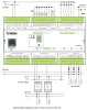
| Notice | 1) Due to the possible interaction of individual inputs, it is necessary to divide the individual circuits as close as possible to the AGND terminal as indicated in Figure 4.1. |
| DI - Parameters of DC binary inputs (group B) | |
| Parameters valid for inputs on the terminals | DI6 – DI11 |
| Number of inputs in group | 6 |
| Common wire | minus |
| Input type (IEC) | Type 1 (IEC) - passive |
| Galvanic separation of inputs from internal circuits | No |
| Diagnostics | indication of energized input by LED on module panel |
| Input voltage for log. 0 | 2,3 V DC min.; 12 V DC max. |
| Input current at log. 1 (typ.) | typ. 5 mA |
| Notice | *) - inputs DI6 and DI7 are connected to common terminals with AO2 and AO3 - the function is selected in the programming environment |
| DI - Parameters of binary AC inputs | |
| Parameters valid for AC inputs on the terminals | HDO |
| Total number of binary AC inputs | 1 |
| Number of groups of AC inputs | 1 |
| Number of AC inputs in group | 1 |
| Organization of binary inputs into groups | 1x DI 230 V AC (DI12) |
| Input type | 230 V AC |
| Galvanic isolation of internal circuits | Yes |
| Input voltage for log. 0 | 0 V AC min., 120 V AC max. |
| Input voltage for log. 1 | 230 V AC typ., 200 V AC min., 250 V AC max. |
| Input current at log. 1 (typ.) | 5 mA typ. |
| Delay from log. 0 to log. 1 | 10 ms |
| Delay from log. 1 to log. 0 | 10 ms |
| HSC - Counter input parameters | |
| The parameters are valid for inputs | DI6-DI11 |
| Special input functions | one-way counter |
| Counter: Input frequency / resolution | 10 kHz / 1 pulse |
| Pulse width | min. 20 μs |
| Delay from log. 0 per log. 1 | 4 μs |
| Delay from log. 1 per log. 0 | 4 μs |
| Range of registers | up to 32 bits, 0 to 4 294 967 296 |
| DO/RO - Organization of binary outputs | |
| Total number of binary outputs | 9 |
| Number of binary output groups | 2 |
| Organization of binary outputs into groups |
8x DO (DO0-DO7) 1x DO (DO8) |
| DO - Parameters of binary transistor outputs (group A) | |
| Parameters valid for the terminals | DO0-DO7, DO8 |
| Number of transistor outputs | 9 |
| Number of output groups | 2 |
| Number of outputs in group | 8 |
| Organization of transistor outputs into groups | 8x DO (DO0-DO7); 1x DO (DO8) |
| Output type | MOSFET (Low-side switch) |
| Galvanic separation from internal circuits | No |
| Diagnostics | indication of energized output by LED on module panel |
| Switching voltage | 10 – 32 V DC |
| Switching current, output load | 0,5 A max. |
| Residual current | max. 10 μA |
| Short circuit protection | current limitation (without signaling) |
| Transistor output protection | ESD, overvoltage, temperature, polarity reversal |
| Special functions (A) | PWM |
| Operating frequency | 20 kHz max. |
| Notice | 1) Check the correct connection of the minus pole of the power supply circuit of the L2 source (Fig. 4.1) to the GDO terminals for the output circuits. If the power supply is not connected correctly, the limit current for disconnecting 150 mA outputs for the whole group - deactivation of outputs DO0-DO8 with signaling of this state by flashing LEDs of the whole group and setting of appropriate OVL bit in binary input group is performed by setting the COVL bit in the DO binary output group from zero to 1. |
| RO - Parameters of binary relay outputs (group A) | |
| Number of relay outputs | 3 |
| Number of output groups | 3 |
| Number of outputs in group | 1 |
| Organization of relay outputs into groups | 1x RO (DO9) + 1x RO (DO10) + 1x RO (DO11) |
| Output type | electromechanical relay, unprotected output |
| Contact type | NO - Normally Open |
| Diagnose | Alarm signaling on panel module |
| Switching current | 16 A max., 100 mA min. |
| Switching voltage | 250 V AC max., 5 V AC min., 30V DC max. |
| Short-term output overload - inrush | 80 A max. (20 ms max.) |
| Contact closing time | typ. 15 ms |
| Contact opening time | typ. 5ms |
| Limit values of switched resistive load | max. 16A at 30 V DC or 230 V AC |
| Switching inductive load limits DC13 | max. 1 A at 30 V DC |
| Switching inductive load limits AC15 | max. 3.5 A at 230 V AC |
| Switching frequency without load | max. 300 switching / min. |
| Switching frequency with rated load | max. 20 switching / min. |
| Mechanical life | min. 20 000 000 cycles |
| Electrical life at maximum resistive load | min. 500,000 cycles |
| Electrical life at maximum load inductive DC13 | min. 50,000 cycles |
| Electrical life at maximum load for UL TV-5 light sources | min. 25,000 cycles |
| Short-circuit protection | No |
| Treatment of inductive load | External RC element, varistor (AC), diode (DC) |
| Notice! | 1) Attention! The insulation strength between contact groups COM1-DO9, COM2-DO10 and COM3-DO11 does not meet the requirements for double insulation. If one group is used for mains voltage, the other groups must not be used for circuits with SELV or PELV voltage! |
| AI - Organization of analog inputs | |
| Total number of analog inputs | 6 |
| Number of inputs per group | 6 |
| Number of analog input groups | 1 |
| Organization of analog inputs into groups | 6x DI/AI (DI0/AI0 - DI5/AI5) |
| Input type | With common clamp |
| Common wire | AGND clamp |
| Galvanic separation from internal circuits | No |
| Diagnostics | signaling overload, disconnection and short-circuiting of the sensor in the status word |
| Type of protection | integrated overvoltage protections |
| External power supply | No |
| Digital resolution | 12 bit |
| Converter type | Approximation |
| Operating modes | periodic input sensing |
| Filtration | low pass filter, digital comb filter 50/60 Hz |
| AI - Analog Input Ranges (Group A) | |
| Passive sensor | Pt1000, W100 = 1,385 (-90 to +400 °C) |
| Passive sensor | Pt1000, W100 = 1,391 (-90 to +400 °C) |
| Passive sensor | Ni1000, W100 = 1,500 (–60 to +200 ° C) |
| Passive sensor | Ni1000, W100 = 1.617 (-60 to +200 ° C) |
| Passive sensor | Resistance transmitter 0-2 kOhm |
| Passive sensor | KTY81-121; PTC thermistor (-55 to + 125 °C) |
| Input impedance in signal range RTD | > 4 kΩ |
| Resistance measurement error - maximum error at 25 ° C | ± 0.5% of full scale |
| Resistance measurement error - temperature coefficient | ± 0.05% of full scale / K |
| Resistance measurement error - non-linearity | ± 0.09% of full scale |
| Resistance measurement error - repeatability at steady conditions | 0.07% of full scale |
| Max. permissible permanent overload of analog input (without damage) | –20 to +30 V (each AI terminal against AGND) |
| Detection of disconnected sensor | yes, in status word, range overflow |
| AO - Analog output parameters | |
| Number of outputs in group | 4 |
| Organization of outputs in groups | 2x AO (AO0-AO1) + 2x AO (DI6/AO1-DI7/AO3) |
| Parameters valid for the terminals | AO0-AO1, DI6/AO1-DI7/AO3 |
| Common wire of group | minus |
| Galvanic isolation from internal circuits | No |
| Output type | active voltage output |
| Type of protection | integrated overvoltage protections |
| Max. permissible permanent overload (without damage) | ± 20 V, each terminal against AGND |
| Converter resolution | 12 bit |
| conversion time | 10 μs |
| Analog output error - maximum error at 25 ° C | ± 2% of full scale |
| Analog output error - temperature coefficient | ± 0.3% of full scale / K |
| Analog output error - linearity | ± 0.7% of full scale |
| Analog output error - repeatability under steady state conditions | ± 0.5% of full scale |
| External power supply | No |
| Voltage output - voltage | 0 - 10 V |
| Voltage output - Resolution 1 LSB | 10,546 mV |
| Voltage output - maximum output current | 10 mA |
| Notice | *) AO2 and AO3 are connected to common terminals DI6 and DI7 - the function is selected in the programming environment |
| Power supply | |
| Nominal supply voltage (V) | 24 V DC |
| Supply voltage, tolerances | 24 V DC, +25%, -15%, SELV |
| Supply voltage when backing up with an external battery | 27 V DC, +10%, –15%, SELV |
| Typical power input | 8 W |
| Maximum power input | 10 W |
| Module thermal/power loss | 7 W |
| Maximum current consumption (mA) | 500 mA |
| Galvanic separation of power supply from internal circuits | No |
| Internal protection | Yes, PTC reversible fuse |
| Description of power supply | Difference between typical and maximum power input is given by possible load of CIB buses and number of switched outputs and CPU load |
| CIB branch power supply - parameters of the built-in master | 1x 100 mA/ 24 V DC |
| Size and weight | |
| Weight approx. | 300 g |
| Product dimensions (width x height x depth) | 158 x 92 x 63 mm |
| Module width in multiples of M (17.5 mm) | 9M |
| Product dimensions (width x height x depth) | 158 x 92 x 63 mm |
| Operating conditions, product standards | |
| Product standard | ČSN EN 61131-2:2008 (idt IEC 61131-2:2007) - Programmable control units |
| Protection class of electrical object | II, according to ČSN EN 61140 ed.3: 2016 (idt IEC 61140:2016) |
| IP rating (Ingress Protection) according to ČSN EN 60529: 1993 (idt IEC 529: 1989) | IP20 |
| Operating areas | Normal, acc. ČSN 33 2000-1 ed.2: 2009 (mod IEC 60354-1:2005) |
| Degree of pollution | 1, according to ČSN EN 60664-1 ed.2:2008 ( idt IEC 60664-1:2007) |
| Overvoltage category installation | II, according to EN 60664-1 ed_2: 2008 (idt IEC 60641-1: 2007) |
| Type of device | Module on DIN rail |
| Working position | Vertical |
| Type of operation (operating frequency) | Continuous |
| Ambient operating temperatures | -20 °C to + 55 °C |
| Operating relative humidity | from 10 % up to 95 % without condensation |
| Operating atmospheric pressure | min. 70 kPa (<3,000 m above sea level) |
| Storage temperatures | –25 °C to +70 °C |
| Electromagnetic compatibility, Mechanical endurance | |
| Electromagnetic compatibility / Emission | A, according to EN 55032 ed. 2: 2017 (idt CISPR 32: 2015) |
| Electromagnetic compatibility / Immunity | min. as required by EN 61131-2: 2007 |
| Sinusoidal vibration endurance | 10 Hz to 57 Hz, amplitude 0,075 mm, 57 Hz to 150 Hz, acceleration 1 G (Fc test according to EN 60068-2-6: 1997 (idt IEC 68-2-6: 1995), 10 cycles per axis.) |
| Installation | |
| Assembly description | Mounting on DIN rail 35 / 7.5 (U) in the switchboard |
| Exchangeable submodules |
Optionale MR-01xx-Submodule mit serieller Kanal 2-Schnittstelle sind im Basismodul CP-1091 auf der mittleren Prozessorkarte an der in Abb. 7.1 markierten Position montiert. Wenn ein Submodul durch eine serielle Kanalschnittstelle hinzugefügt oder ersetzt werden muss, müssen die Verriegelungen am unteren Teil der Abdeckung gelöst, der Sockel entfernt, die untere und mittlere Platte der Platinenbaugruppe entfernt und das Submodul in der vorbereiteten Position auf der Mittelplatte montiert werden - achten Sie auf die richtige Ausrichtung! Vor dem Zusammenbau muss zuerst die obere Platte der Baugruppe von der Abdeckung entfernt werden (indem Sie die linke Seite der Abdeckung leicht biegen und vorsichtig auf den Ethernet-Anschluss drücken, lösen Sie die Platine von den Verriegelungen oben auf der Abdeckung). Setzen Sie die obere Platte in die Gabeln auf der mittleren Platte ein, setzen Sie die gesamte Baugruppe in den Sockel ein und schieben Sie sie zusammen in die Abdeckung. Die obere Platte muss zwischen den Verriegelungsnasen an der Seite der Abdeckung und den Verriegelungen am Sockel in die Löcher an der Seite der Abdeckung passen. |
| Connection | |
| Connection of power and system communication | connector with 2.5 mm2 screw terminal |
| Connection of inputs / outputs | connector with screw terminal 2.5 mm2 |
| Ethernet | RJ-45 |
| Serial channels | screw-type connector 9x 2.5 mm2 |
| Module operation | |
| Module configuration | The module is operated, set up and diagnosed from the Mosaic development environment. |
| Commissioning | The module is ready for operation after connecting the supply voltage. The MODE button is available on the module panel to display the currently set Ethernet IP address. The parameters of all interfaces are set in the Mosaic development environment. |
| Commissioning | The module is ready for operation after connecting the supply voltage. There is a MODE button on the module panel to display the currently set Ethernet IP address. The parameters of all interfaces are set in the Mosaic development environment. The exact setting procedure is given in the TXV00410 documentation. Other activities (programming, application debugging, etc.) are performed in the Mosaic development environment. |
| Module diagnostics | The basic diagnostic system of the module is part of its standard software. It has been in operation since the module power was turned on and works independently of the user. Diagnosed error states of the module and connected peripheral modules of the assembly are signaled on the display module and are available for processing by the master system. For more detailed information, see TXV00410. |
| Maintenance | |
| Description | The module does not require any maintenance under general installation conditions. The operations in which a part of the module has to be dismantled must always be carried out with the supply voltage disconnected. |
| Warning | Because the module contains semiconductor components, it is necessary to follow the principles for working with electrostatic sensitive components when handling the removed cover. It is not allowed to touch the printed circuit boards directly without protective measures. |
| Warranty | |
| Generally | Warranty and complaint conditions are governed by the Terms and Conditions of Teco a.s. |
| Notice | You must meet all the conditions of this documentation before turning on the system. The system must not be put into service unless it has been verified and confirmed that the machinery meets the requirements of Directive 89/392 / EEC, in so far as it applies to it. Documentation subject to change. |
HW documentation
CP-1091/1096 Basic Documentation
286.88 kB, (CS, EN)
User manuals
Foxtrot1 - User's Guide, cze, , TXV00410_01
3.40 MB
Foxtrot1 - User Manual (en), TXV00410_02
4.30 MB
Files for designers
CP-1091/1096 technical drawing 1 DWG
152.32 kB
CP-1091/1096 technical drawing 1 DXF
435.87 kB
CP-1091/1096 - technical drawing 2 DWG
59.55 kB
CP-1091/1096 - technical drawing 2 DXF
100.92 kB
- CH1 communication interface of the CP-1003 and CP-1091, RS485 basic modules - The serial interface of the basic CH1 module CP-1003 and CP-1091 is firmly fitted with the RS-485 interface without galvanic isolation (i.e. the interface signals have galvanic connection with the module power supply, with the CIB interface, th...
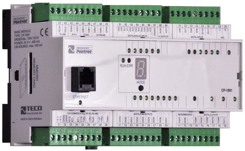
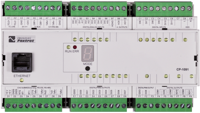
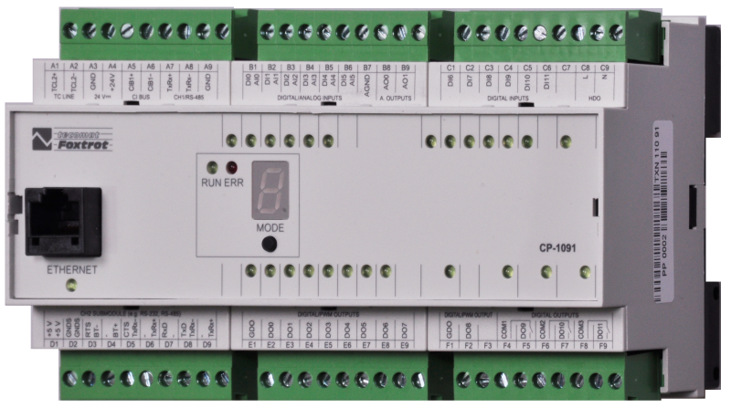
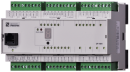
- CP-1091 - The CP-1091 is the basic module of the Foxtrot control system. The standard version is in a 9M housing on a DIN rail (for the housing dimensions, see Chapter 13.2.1 9M housing on a DIN rail ), and it is fitted with six removable terminal blocks....
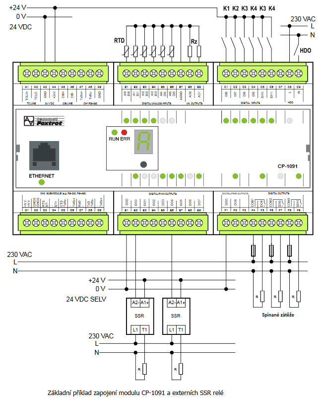
- Connection of CP-1091 for efficient control of energy produced from PV and HFVE - The basic variant of the Foxtrot system for these applications is a new module CP-1091 , which is equipped with up to 9 outputs for direct continuous control of electric heating, as well as 3 outputs for switching loads, it is possible to connect u...
- MR-0105, MR-0106, MR-0115, fitted with CP-1000, CP-1001, CP-1003, CP-1091 - Tab. 1: Terminating of CH2, CH3 and CH4 communication channels for CP-10x0 Terminal block D Terminal MR-0105 MR-0106 MR-...
- Controlling water heating with the CP-2091 using an SSR switch - ...ater heating using SSR relays. For further details and information on control, see, for example, the article " Connection of CP-1091 for efficient control of energy produced from PV and HFVE " Fig. 1 Basic example of connecting the...
- Power dissipation of modules for calculation of switchboard heating - ...1xSCH, 10xAI/DI, 2xAI, 4xAO, 7xRO, 4xSSR, 1xCIB CP-1018 10,0 W TXN 110 91 CP-1091, CPU, ETH100/10, 1x RS232, 1xSCH, 6xAI/DI, 6xDI, 1x DI/230VAC; 2xDI/230VAC,9xDO; 3xRO, 1xCIB CP-1091...
- MR-0161 - CAN interface, with galvanic isolation - ...CP-10x5 CP-10x6 CP-10x8 CP-1000 CP-1003 CP-1091 Signal Type of signal Terminals...
- MR-0160 - 2x CAN interface, with galvanic isolation - ...CP-10x4 CP-10x5 CP-10x6 CP-10x8 CP-1000 CP-1091 Signal Type of signal Terminals...
- MR-0124 - RS-422 interface, with galvanic isolation - ...CP-10x4 CP-10x5 CP-10x6 CP-10x8 CP-1000 CP-1091 Signal Type of signal Usage...
- MR-0114 - RS-485 interface, with galvanic isolation - ...CP-10x5 CP-10x6 CP-10x8 CP-1000 CP-1003 CP-1091 Signal Type of signal Usage...
- MR-0104 - the RS-232 interface, with galvanic isolation - ...CP-10x5 CP-10x6 CP-10x8 CP-1000 CP-1003 CP-1091 Signal Type of signal Usage...
- Communication interface CH2, using optional submodules - ...available in several variants, in accordance with the basic module type: Fig. 1 for the basic modules CP-1000 -1001 and CP-1091 Fig. 2 for the basic module CP-1003 Fig. 3 for the basic modules CP-10x4, CP-10x5. Fig. 4 for the basi...
- DMX device control, connection to the CH4 interface of the CP-1000 module - The following example describes the connection of the DMX bus to the CH4 communication interface of the CP-1000 . basic module. In this way it is possible to control up to 512 devices on the DMX bus from the user program of the Foxtrot system. Supp...
No data available.