


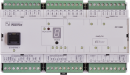

CP-1000TXN 110 00
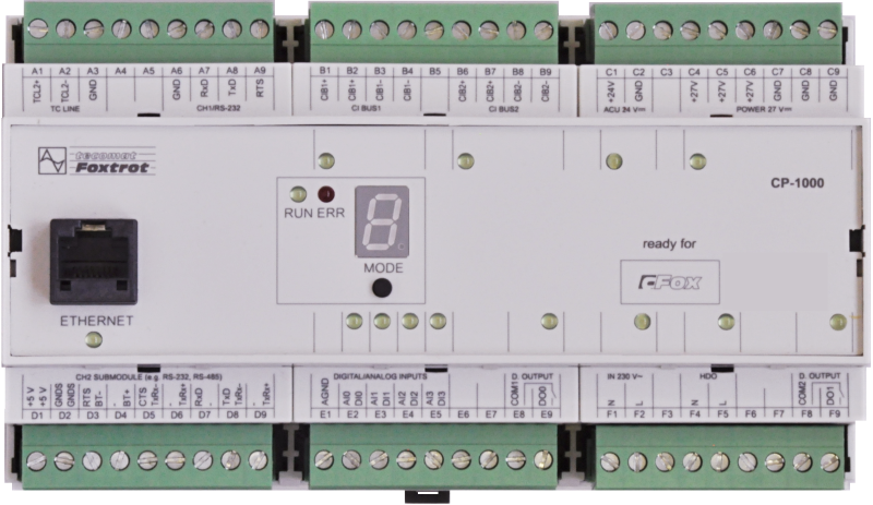
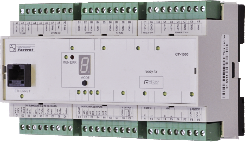
CP-1000, CPU, ETH100/10, 1x RS232, 1xSCH, 4xAI/DI, 2xDI/230VAC, 2xRO, 2xCIB
| DI | 2x DI (230 V AC) |
|---|---|
| DI/AI | 4x DI/AI |
| DO | 2x RO |
| AI | |
| AO | |
| COM | 1x ETH 10/100 1x RS-232 1x freier Steckplatz für CH2 1x TCL2-Master 2x CIB-Master |
| SENSOR |
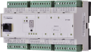
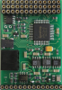
| Bild | Produktvarianten | Variantenbeschreibung |
|---|---|---|

|
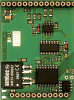
CP-1000 | Anwendungsprogrammspeicher: 192 kB + 64 kB |

|
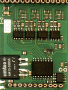
CP-1001 | Anwendungsprogrammspeicher: 384 kB + 64 kB |
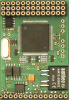
Das Basismodul CP-1000 ist eines der Basismodule (ZM) der modularen programmierbaren Steuerung der Foxtrot-Serie.
Das Basismodul CP-1000 ist ausgestattet mit:
- vier Mehrzweckeingänge, von denen jeder entweder analog oder binär verwendet werden kann
- zwei Binäreingänge mit einem Spannungspegel von 230 V AC
- zwei separate Relaisausgänge.
Das Basismodul CP-1000 ist mit einer Zentraleinheit (CPU) der K-Serie ausgestattet, die für Anwendungen mit Leistungsanforderungen ausgelegt ist. Es enthält gesicherten CMOS-RAM für Benutzerprogramme, Daten, Tabellen, Benutzerregister und DataBox, Flash-Speicher für die Sicherung von Benutzerprogrammen, Steckplatz für MMC / SD / SDHC-Speicherkarte, Echtzeitschaltung ,.
Es verfügt außerdem über eine Ethernet-Schnittstelle, zwei serielle Kanäle (einer mit einer festen RS-232-Schnittstelle, der andere mit einer Position für optionale Submodule), zwei Kommunikationskanäle mit einer CIB-Schnittstelle zum Anschließen externer Peripheriegeräte (2x1A) und eine TCL2-Systemschnittstelle zum Anschließen von Erweiterungsmodulen, die zunehmen Anzahl der E / A-Systeme.
| Bestellnummer | TXN 110 00 |
|---|---|
| Teco-Code | TXN 110 00 |
| Kategorien | Foxtrot 1 - Grundmodule |
| Stichworte | Verkauf und Produktion beendet |
| Systemparameter der Zentraleinheit | |
|---|---|
| Reihe der Zentraleinheit | K |
| Anwenderprogrammspeicher | 192 + 64 kB |
| Speicher für Benutzervariablen / einschließlich RETAIN-Variablen | 64 kB/32 kB |
| Anweisungslänge | 2 × 10 Bytes |
| Sicherung des Programmquellcodes in der SPS | Ja, im Programm-Backup-Speicher (EEPROM) |
| Online-Programmwechsel in der SPS | Ja, einschließlich Änderungen in I / O-Konfiguration |
| Speicher für die Projektarchivierung - intern | 2 MB |
| DataBox - zusätzlicher interner Datenspeicher | 512 kB |
| Optionaler Speicherkartensteckplatz | SD - Card Slot |
| Zykluszeit pro 1k logischer Anweisunge | 0,2 ms |
| Entwicklungsumgebung | Mosaic |
| Programmiersprachen | ST, IL, LD, FBD, SFC, CFC |
| RAM- und RTC-Backup 1) ohne / mit Pufferbatterie | typ. 500 h / typ. 20.000 Stunden |
| Integrierter Webserver | Ja |
| Integrierter Datenlogger | Ja |
| Zugriff auf SPS-Variablen über Web-API | Ja |
| Beachten |
1) Gilt für das Basismodul ohne Stromversorgung, werden die Notstromkreise beim Einschalten der Stromversorgung getrennt 2) Die serielle Schnittstelle CH1 ist permanent mit einer RS-485-Schnittstelle ausgestattet. Die serielle Schnittstelle Typ CH2 bis CH4 ist über austauschbare Submodule wählbar |
| COM - Kommunikation - IP/Ethernet | |
| Ethernet 10/100 Mb (ETHx) | 1 |
| Verfügbare Systemmodi an ETH und WLAN | UNI, PC, PLC, PLD |
| COM - Serielle Kanäle | |
| max. Anzahl optionaler serieller Kanäle im Basismodul | 4 |
| max. Anzahl erweiternder serieller Kanäle auf dem TCL2-Bus | 6 |
| Anzahl der internen seriellen RS-232-Kanäle | 1 |
| Verfügbare Systemmodi auf CH5-10 | UNI, CSJ (CAN) |
| COM - Systembusse | |
| TCL2 - System-E/A-Bus | 1x TCL2 master |
| TCL2 – Bereich eines Zweigs des System-E/A-Busses | 10 E / A-Module + 4 Bedienfelder + 6 serielle Kanäle |
| Kommunikationsgeschwindigkeit des System-E / A-Busses | 345 kbps |
| Abschlusswiderstand des System-E / A-Busses | 120 Ω |
| CIB - Common Installation Bus (R): Installations-E/A-Bus | 2x CIB master (2x 1 A) |
| CIB - Adressbereich eines Zweiges des Installationsbusses | 32 CFox-E/A-Module |
| DI - Organisation von Binäreingängen | |
| Gesamtzahl der binären Eingänge | 4 |
| Anzahl der binären Eingabegruppen | 1 |
| DI - Parameter der Binäreingänge DC (Gruppe A) | |
| Anzahl der Eingänge pro Gruppe | 4 |
| Warnung | Die Eingänge DI0 - DI3 können alternativ als Analogeingänge (AI0 - AI3) verwendet werden. Die Auswahl wird für einzelne Eingaben aus der Mosaic-Entwicklungsumgebung getroffen. Aufgrund der möglichen Zunahme von Interferenzen bei Verwendung von Analogeingängen ist es nicht wünschenswert, den gemeinsamen Draht der Binäreingangsschalter an die AGND-Klemme anzuschließen - verwenden Sie die GND-Klemme C. |
| DI - Parameter der binären AC-Eingänge | |
| Gesamtzahl der binären AC-Eingänge | 2 |
| Organisation der Binäreingänge in Gruppen | 2x (IN230V, HDO) |
| Eingangsspannung für log. 1 | 230 V AC typ., 200 V AC min., 250 V AC max. |
| Eingangsstrom bei Log. 1 (typ.) | 5 mA typ. |
| Verzögerung vom log. 0 zum log. 1 | 10 ms |
| Verzögerung vom log. 1 zu log. 0 | 10 ms |
| RO - Parameter der binären Relaisausgänge (Gruppe A) | |
| Parameter gültig für die Terminals | DO0, DO1 |
| Anzahl der Relaisausgänge | 2 |
| Anzahl der Ausgabegruppen | 2 |
| Anzahl der Ausgänge in Gruppe | 1 |
| Organisation der Relaisausgänge in Gruppen | 1x (DO0) +1 (DO2) |
| Ausgangstyp | elektromechanisches Relais, ungeschützter Ausgang |
| Kontakttyp | NO - (Normally Open) Umschalten |
| Diagnose | Alarmsignalisierung ein Panel-Modul |
| Schaltstrom | 3 A max., 100 mA min. |
| Schaltspannung | 250 V AC max., 5 V AC min., 30V DC max. |
| Kontaktschlusszeit | typ. 10 ms |
| Kontakt Öffnungszeit | typ. 4 ms |
| Grenzwerte der geschalteten ohmschen Last | Max. 3A bei 30 V DC oder 230 V AC |
| Induktive Lastgrenzen schalten DC13 | max. 1 A bei 30 V DC |
| Induktive Lastgrenzen schalten AC15 | Max. 3 A bei 230 V AC |
| Schalthäufigkeit bei Nennlast | Max. 20 Schaltungen / Min. |
| Mechanische Lebensdauer | min. 5.000.000 Zyklen |
| Elektrische Lebensdauer bei maximaler ohmscher Last | min. 100,000 cycles |
| Elektrische Lebensdauer bei maximaler Last induktiv DC13 | min. 100.000 Zyklen |
| Elektrische Lebensdauer bei maximaler Belastung induktiv AC15 | min. 100.000 Zyklen |
| Behandlung der induktiven Last | Externes RC-Glied, Varistor (AC), Diode (DC) |
| Isolationsspannung zwischen Ausgängen und internen Schaltkreisen | 3750 V AC |
| Isolationsspannung zwischen Ausgangsgruppen untereinander | 3750 V AC |
| AI - Organisation der Analogeingänge | |
| Gesamtzahl der Analogeingänge | 4 |
| Anzahl der Eingänge pro Gruppe | 4 |
| Anzahl der analogen Eingangsgruppen | 1 |
| Organisation von Analogeingängen in Gruppen | 4x (AI0/DI0-AI3/DI3) |
| Gemeinsamer Draht | Minus |
| Galvanische Trennung von internen Stromkreisen | Nein |
| Diagnostik | signalizace přetížení, odpojení a zkratování čidla ve stavovém slově |
| Zündschutzart | integrierter überspannungsschutz |
| Externe Stromversorgung | Nein |
| Digitale Auflösung | 12 bit |
| Konvertertyp | Annäherung |
| Filtration | Tiefpassfilter, digitales Kammfilter 50/60 Hz |
| AI - Analoge Eingangsbereiche (Gruppe A) | |
| Passive Sensor | Pt1000, W100 = 1.385 (-90 bis +400 °C) |
| Passive Sensor | Pt1000, W100 = 1.391 (-90 bis +400 °C) |
| Passive Sensor | Ni1000, W100 = 1.500 (–60 bis +200 ° C) |
| Passive Sensor | Ni1000, W100 = 1,617 (-60 bis +200 ° C) |
| Passive Sensor | Widerstandsmessumformer 0-2 kOhm |
| Passive Sensor | Widerstandsmessumformer 0-200 kOhm |
| Passive Sensor | KTY81-121; PTC Thermistor (-55 bis + 125 °C) |
| Passive Sensor | NTC Thermistor NTC 12k / 25 °C (-40 bis + 125 °C) |
| DI: Spannungsfreier Kontakt | 0 wenn> 1,5 kOhm, 1 wenn <0,5 kOhm |
| Widerstandsmessfehler - maximaler Fehler bei 25 ° C | ± 0,5% vom Skalenendwert |
| Widerstandsmessfehler - Temperaturkoeffizient | ± 0,05% vom Endwert / K |
| Widerstandsmessfehler - Nichtlinearität | ± 0,09% vom Skalenendwert |
| Widerstandsmessfehler - Wiederholgenauigkeit unter stationären Bedingungen | 0,07% vom Skalenendwert |
| Max. zulässige dauerhafte Überlastung des Analogeingangs (ohne Beschädigung) | –20 bis +30 V (jeder AI-Anschluss gegen AGND) |
| Erkennung eines unterbrochenen Sensors | ja, Überlaufmeldung |
| Stromversorgung | |
| Nennversorgungsspannung (V) | 24 V DC |
| Versorgungsspannung, Toleranzen | 24 V DC, +25%, -15%, SELV |
| Versorgungsspannung mit externer Batterieunterstützung | 27 V DC, +10%, –15%, SELV |
| Typische Leistungsaufnahme | 10 W |
| Maximaler Stromverbrauch | 75 W |
| Wärme-/Leistungsverlust des Moduls | 6 W |
| Maximaler Stromverbrauch (mA) | 3,125 A |
| Galvanische Trennung der Stromversorgung von internen Schaltkreisen | Nein |
| Interner Schutz | Ja, PTC-Wendesicherung |
| Beschreibung der Stromversorgung | Der Unterschied zwischen typischer und maximaler Leistungsaufnahme ergibt sich aus der möglichen Belastung der CIB-Busse und der Anzahl der Schaltausgänge und der CPU-Belastung |
| CIB-Zweigversorgung - Parameter des eingebauten Masters | 2x 1 A/ 24-27 V DC |
| Batterieparameter | 24 V (2x 12V), max. 18 Ah |
| Kontinuierliches Laden | Ja, über die Ladeschaltung im Basismodul |
| Interner Pufferbatterieschutz | Ja |
| Ausgehend von Pufferbatterie | Nein |
| Abmessungen und Gewicht | |
| Gewicht ca. | 300 g |
| Produktabmessungen (Breite x Höhe x Tiefe) | 158 x 90 x 62 mm |
| Modulbreite in Vielfachen von M (17,5 mm) | 9M |
| Modulbreite | 158 mm |
| Modulhöhe | 90 mm |
| Modultiefe | 63 mm |
| Produktabmessungen (Breite x Höhe x Tiefe) | 158 x 90 x 62 mm |
| Betriebsbedingungen, Produktnormen | |
| Produktstandard | ČSN EN 61131-2: 2008 (idt IEC 61131-2: 2007) - Programmierbare Steuereinheiten |
| Elektrische Schutzklasse | II, nach ČSN EN 61140 ed.3: 2016 (idt IEC 61140:2016) |
| IP-Schutzgrad gemäß ČSN EN 60529: 1993 (idt IEC 529: 1989) | IP20 |
| Arbeitsbereiche | Normal gemäß ČSN 33 2000-3: 1995 (mod IEC 364-3: 1993) |
| Grad der Verschmutzung | 1, gem. ČSN EN 60664-1 ed.2:2008 ( idt IEC 60664-1:2007) |
| Überspannungskategorie Installation | II, gemäß EN 60664-1 ed_2: 2008 (idt IEC 60641-1: 2007) |
| Art des Geräts | Modul auf DIN-Schiene |
| Arbeitshaltung | Vertikal |
| Art des Betriebs (Betriebsfrequenz) | Permanent |
| Umgebungsbetriebstemperaturen | -20 °C bis + 55 °C |
| Relative Luftfeuchtigkeit im Betrieb | 10% bis 95% ohne Kondensation |
| Betriebsatmosphärendruck | Mindest. 70 kPa (<3.000 m über dem Meeresspiegel) |
| Lagertemperaturen | -25 °C bis + 70 °C |
| Elektromagnetische Verträglichkeit, mechanische Beständigkeit | |
| Elektromagnetische Verträglichkeit / Emissionen | A, gemäß EN 55022: 1999 (mod CISPR22: 1997) |
| Emissionen - Hinweis | Dieses Produkt kann in Bereichen, in denen Radio- und Fernsehempfänger voraussichtlich weniger als 10 m entfernt sind, Funkstörungen verursachen. In diesem Fall kann der Benutzer aufgefordert werden, geeignete Maßnahmen zu ergreifen |
| Elektromagnetische Verträglichkeit / Störfestigkeit | Mindest. gemäß EN 61131-2: 2007 |
| Widerstand gegen sinusförmige Schwingungen | 10 Hz bis 57 Hz Amplitude 0,075 mm, 57 Hz bis 150 Hz Beschleunigung 1 G (Fc-Test gemäß EN 60068-2-6: 1997 (idt IEC 68-2-6: 1995), 10 Zyklen in jeder Achse.) |
| Verpackung, Transport, Lagerung | |
| Beschreibung | Das Modul wird gemäß den internen Verpackungsanweisungen in einer Papierbox verpackt. Das Paket enthält auch diese Dokumentation. Die Umverpackung erfolgt gemäß dem Umfang der Bestellung und der Transportart der Transportverpackung, die mit Transportetiketten und anderen für den Transport erforderlichen Daten versehen ist. Der Transport des Produkts auf eigene Faust muss mit einem abgedeckten Transportmittel erfolgen, das auf der Verpackung mit einem südeuropäischen Etikett versehen ist. Die Box muss so gelagert werden, dass spontane Bewegungen und Beschädigungen der Außenverpackung vermieden werden. Das Produkt darf während des Transports und der Lagerung keiner direkten Witterung ausgesetzt werden. Der Transport ist bei Temperaturen von -25 ° C bis 70 ° C, einer relativen Luftfeuchtigkeit von 10% bis 95% (nicht kondensierend) und einem minimalen Luftdruck von mehr als 70 kPa zulässig. Das Produkt darf nur in Reinräumen gelagert werden, die frei von leitendem Staub, aggressiven Gasen und Dämpfen sind. Die am besten geeignete Lagertemperatur beträgt 20 ° C. |
| Installation | |
| Montagebeschreibung | Das Basismodul wird vertikal auf der U-Schiene ČSN EN 50022 montiert. Die Installation der Baugruppe (Basismodul und Peripheriemodule, falls zutreffend) erfolgt gemäß TXV 004 10. |
| Achtung! | Das Gerät kann Teile mit gefährlichen Spannungen enthalten, Abdeckungen entfernen oder Kabel manipulieren oder die entsprechenden Stromkreise trennen oder die Stromversorgung ausschalten! |
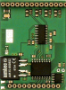
| Austauschbare Submodule | Die optionalen MR-01xx-Submodule mit serieller Schnittstelle für Kanal 2 werden auf der Mittelplatte im CP-10x0-Grundmodul an der in Abb. 7.1 angegebenen Position montiert. Wenn Sie ein Submodul durch eine serielle Kanalschnittstelle ersetzen oder hinzufü |
| Modulbetrieb | |
| Modulkonfiguration | Das Modul wird in der Mosaic-Entwicklungsumgebung bedient, eingestellt und diagnostiziert. |
| Inbetriebnahme | Das Modul ist nach dem Anschließen der Versorgungsspannung betriebsbereit. Die MODE-Taste ist auf dem Modulfeld verfügbar, um die aktuell eingestellte Ethernet-IP-Adresse anzuzeigen. Die Parameter aller Schnittstellen werden in der Mosaic-Entwicklungsumgebung festgelegt. |
| Moduldiagnose | Das grundlegende Diagnosesystem des Moduls ist Teil seiner Standardsoftware. Es arbeitet ab dem Einschalten des Moduls und unabhängig vom Benutzer. Die Diagnosestatus des Moduls und der angeschlossenen Peripheriemodule der Baugruppe werden gemeldet |
| Wartung | |
| Beschreibung | Das Modul ist unter allgemeinen Installationsbedingungen wartungsfrei. |
| Garantie | |
| Allgemein | Die Garantie- und Reklamationsbedingungen unterliegen den Allgemeinen Geschäftsbedingungen von Teco a.s. Warnung: Vor dem Einschalten des Systems müssen alle Bedingungen dieser Dokumentation erfüllt sein, da sonst der Schutz des Geräts beeinträchtigt werden kann. Das System darf nicht eskortiert werden, es sei denn, es wurde überprüft und bestätigt, dass die Maschinen mit dem Foxtrot-System gegebenenfalls die Anforderungen der Richtlinie 89/392 / CEE erfüllen. Alle Reparaturen und Wartungen des Produkts werden ausschließlich vom Hersteller oder von einer autorisierten Person durchgeführt. Der Systeminstallateur ist für die Sicherheit des Systems verantwortlich. |
Bedienungsanleitung
Foxtrot1 Series Übersicht - Benutzerhandbuch, cze
3,40 MB
Foxtrot1 – Benutzerhandbuch (en), TXV00410_02
4,30 MB
Dateien für Designer
CP-1000 technische Zeichnung DWG
158,77 kB
CP-1000 technische Zeichnung DXF
451,10 kB
CP-1001 technische Zeichnung DWG
154,84 kB
CP-1001 technische Zeichnung DXF
451,86 kB
MR-0114
TXN 101 14
MR-0114, RS-485 galvanische Trennung, Eigenquelle und automatische Identifizierung
MR-0124
TXN 101 24
MR-0124, RS-422, mit eigener Stromversorgung und automatischer Identifizierung, galvanische Trennung
MR-0105
TXN 101 05
MR-0105, 1x RS-485, 2x RS-232 (nur FOXTROT), GO mit eigener Stromversorgung und automatischer Identifizierung
MR-0106
TXN 101 06
MR-0106, 2x RS-485, 1x RS-232 (nur FOXTROT), mit eigener Stromversorgung und automatischer Identifizierung, galvanische Trennung
MR-0115
TXN 101 15
MR-0115, 3x RS-485 (nur FOXTROT), mit eigener Stromversorgung und automatischer Identifizierung

MR-0161
TXN 101 61
MR-0161, 1x CAN (SJA1000, Philips), mit eigener Stromversorgung, galvanische Trennung
MR-0160
TXN 101 60
MR-0160, 2x CAN (SJA1000, Philips), mit eigener Stromversorgung, galvanische Trennung
MR-0152
TXN 101 52
MR-0152, PROFIBUS DP-Slave, mit eigener Spannungsversorgung, galvanische Trennung
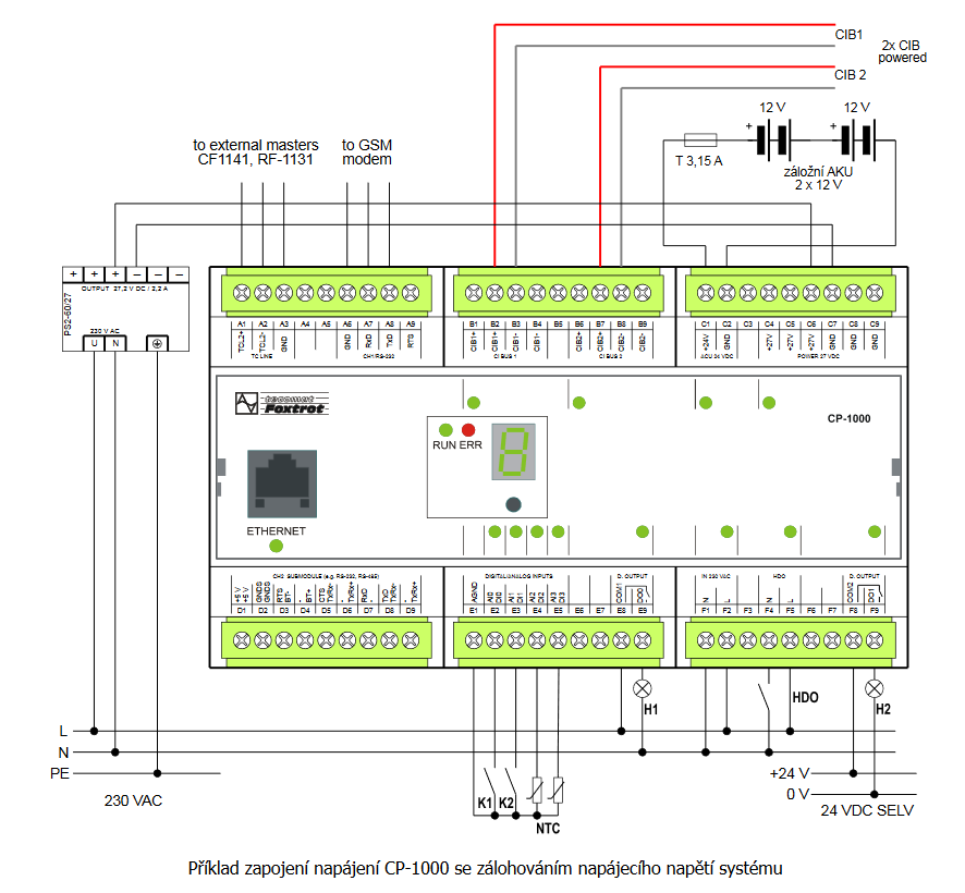
- CP-1000, a power supply with a backup - If the Foxtrot (in this case CP-1000) control system is also utilized for electronic security signalization, it is vital to use a battery backup. The power supply must be able to supply power to the electronic security system in all its modes for t...
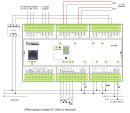
- CP-1000, power supply without a backup - The CP-1000 represents the simplest variant of the basic module for home installations. The basic module is supplied from a 24 VDC source. Both CIB branches (B connector) are supplied from the basic modules, which means that no decoup...
- Connecting a three-command switching element to the CP-1000 inputs - The following figure shows an example of connecting a three-command switching element to the CP-1000 module, which has information on the validity of the low tariff; the power control of the blocked appliances can also be provided directly by contra...
- DMX device control, connection to the CH4 interface of the CP-1000 module - The following example describes the connection of the DMX bus to the CH4 communication interface of the CP-1000 . basic module. In this way it is possible to control up to 512 devices on the DMX bus from the user program of the Foxtrot system. Supp...
- Direct connection of the CP-1000 inputs to the switching element output - The following example shows a direct connection of two-command switching element to the CP-1000 basic module, whose power controls the blocked appliances and which also has information about the validity of the low tariff. The connection covers most...
- CP-1000, CP-1001 - ...from the controlled technology and where is a higher number of peripheral modules on CIB buses, it is preferable to use the CP-1000 basic module. In extensive applications, where complex application software is expected, as well as multiple dev...
- MR-0105, MR-0106, MR-0115, fitted with CP-1000, CP-1001, CP-1003, CP-1091 - Tab. 1: Terminating of CH2, CH3 and CH4 communication channels for CP-10x0 Terminal block D Terminal MR-0105 MR-0106 MR-...
- Energy saver in the hotel room (the card holder) VingCard - ...ning the RFID card holder state can be done by any DI of the Foxtrot system. The 230 VAC inputs (e.g. the CP-1000 ) can be used directly, without a conversion relay, the 230 V input of the CP-1000 module can be connected direc...
- Measurement of 4x 1f production or consumption, electricity meter PA 144 - ...chapter. Fig. 1 Example of connection of 4x measurement of 1f network by electricity meter PA 144 connected to CH2 CP-1000 See this article for wiring notes....
- Foxtrot basic module power supply - ...ing on the type of basic module); without the fitted submodule it is around 2 ÷ 6 W. This does not apply to the basic CP-1000 and CP-1001 modules; for information on their power supply, see Chapter 2.7.1 . A table with the powe...
- Connecting the JABLOTRON 100 system - ...e connected to the Foxtrot system via the RS-485 serial interface to the communication channel, e.g. the CH2 channel of the CP-1000 basic module (see the example below) or to an external communication module SC-1101 . The JA-121T module also re...
- Connecting an indoor siren - ...he ceiling, in a less accessible place. The following example shows the connection of the SA-913 T internal siren to the CP-1000 basic module with a standard power supply with a backup - the PS2-60/27 power supply and 2 x 12 V batteries....
- C-DM-0402M-RLC - ...their dissipated heat does not effect modules with precise analogue measurement, or the basic module of the system (e.g. the CP-1000, as it is equipped with electronic thermal fuses of CIB buses, which should prevent reaching a maximum permissible cu...
- Control of SONESSE 30 RS485 drives manufactured by SOMFY - ...ected to the 2-pin connector. Fig. 1. An example of connecting the SONESSE 30 RS485 motor to CH2 interface of the CP-1000 module Notes: Cables with the RS-485 interface and power supply are part of the motor; the...
- Foxtrot 2 - Shifts to two! - ...number of inputs and outputs and two CIB masters with full power supply for both branches, which corresponds to the original CP-1000. CP-2007 carries a new combination I / O with 14 universal DI / AI inputs, of which 4 can be as fast counters and 1 &...
- FOXTROT – the basic and peripheral modules, power supply - ...uts and outputs.The development tools used for its programming include the Mosaic environment, and in the case of the basic CP-1000 module, the FoxTool environment can also be used. In addition to the Ethernet interface terminal/socket, the fr...
- System power supply – power sources - ...alue). Determination of the power source output: The power supply alone (without the CIB buses) of the CP-1000 can utilize a supply with the power output of min. 15 W (we recommend the DR-15-24). If other circuits are also power...
- Power dissipation of modules for calculation of switchboard heating - ...KB-0552, TCL2 Converter MM fiber optic - 1 piece KB-0552 1,2 W TXN 110 00 CP-1000, CPU, ETH100/10, 1x RS232, 1xSCH, 4xAI/DI, 2xDI/230VAC, 2xRO, 2xCIB CP-1000 6,0 W...
- MR-0104 - the RS-232 interface, with galvanic isolation - ... CP-10x4 CP-10x5 CP-10x6 CP-10x8 CP-1000 CP-1003 CP-1091 Signal Type of signal...
- Communication interface CH1 of the basic modules CP-10xx, RS-232 - ...pply, the CIB bus and the TCL2 (it is also common with the negative common terminal of DI/AI inputs). The basic CP-1000 module has the GND terminal also available at A6 terminal. RTS is a control signal (output), which is us...
- Communication interface CH2, using optional submodules - ...the terminals is available in several variants, in accordance with the basic module type: Fig. 1 for the basic modules CP-1000 -1001 and CP-1091 Fig. 2 for the basic module CP-1003 Fig. 3 for the basic modules CP-10x4, CP-10x5. F...
- MR-0114 - RS-485 interface, with galvanic isolation - ... CP-10x4 CP-10x5 CP-10x6 CP-10x8 CP-1000 CP-1003 CP-1091 Signal Type of signal...
- MR-0124 - RS-422 interface, with galvanic isolation - ... CP-10x4 CP-10x5 CP-10x6 CP-10x8 CP-1000 CP-1091 Signal Type of signal Usage...
- MR-0160 - 2x CAN interface, with galvanic isolation - ... CP-10x4 CP-10x5 CP-10x6 CP-10x8 CP-1000 CP-1091 Signal Type of signal...
- MR-0161 - CAN interface, with galvanic isolation - ... CP-10x4 CP-10x5 CP-10x6 CP-10x8 CP-1000 CP-1003 CP-1091 Signal Type of signal...
- PX-7811, PX-7812 submodules (CH2 Foxtrot fitted with DI and DO) - If you want to expand the Foxtrot basic modules CP-10x4, 10x5-CP and CP-1000 with several binary inputs, or possibly also outputs, and at the same time the CH2 is not used, then you can use the PX-7811 and 7812 submodules. N.B.: The PX-7811 a...
- CIB characteristics - ...wering the bus is provided by a standard 27.2 VDC or 24 VDC source connected to the bus via internal separation circuits ( CP-1000 , CF-1141 ) or an external decoupling module C-BS-0001M . The power supply can also be used for powering th...
- CIB power supply – principles, optimization - ...well as the CIB internal master, and in fact the whole Foxtrot basic module, which contains an internal master (e.g. the CP-1000 ) and an external decoupling module,the C-BS-0001M , should be connected directly in the power supply output (...
- Internal CIB master at the CP-10xx - ...decoupling module must be connected to the CIB (maximum total current of modules on the bus 1A). The basic modules CP-1000 and CP-1001 are equipped with two CIB internal masters, including an internal decoupling circuit with full power o...
- CF-1141 external CIB master - ...power inputs of all peripheral modules in both CIB buses. The same requirements should be applied to power supply of the CP-1000 basic modules. Maximum load of each CIB bus (branch) is 1 A. The power supply has to be chosen with respect...
- Serial communication interfaces RS-232, RS-485, RS-422, CAN and others - The CP-1000 basic module (similarly to other Foxtrot basic modules, e.g. CP-1006) is always fitted with the RS-232 communication interface terminated on the CH1 channel; there is also an option to fit replaceable submodules to the channel CH2, wher...
- Connecting the SAMSUNG air conditioning units - ...e FOXTROT system Fig. 2. An example of connecting the MIM-B13A (SAMSUNG) communication interface to the CP-1000 Notes: The CH2 communication interface of the CP-1000 basic module in the example i...
- Connecting the LG air conditioning units - ...to the FOXTROT system Fig. 2. An example of connecting the PI485 (LG) communication interface to the CP-1000 Notes: The CH2 communication interface of the CP-1000 basic module in the example i...
- First generation Tecomat Foxtrot PLC - ...re Filter by parameters CP-1000 CP-1000-Basic module Foxtrot, 2x CIB master powered [ DI: 6, DO: 2, Type: PLC-Foxtrot, Manufacturer: Teco, D...
- Analog input - Can I use AI of CP-1000 PLC with input 0-10V? Can I use AI of C-IR-0303M with input 0-10V? In case it is not possible which module I could buy? Regards
- Cp1000 to cp2000 apple home bridge - ...000), HomeBridge 1 spolupracuje s PlcComS 1. PlcComS 2 běží na 127.0.0.1, port 5011 (CP-2000), IP adresa PLC je IP adresa CP-1000. HomeBridge 2 je navázán na PlcCom2. Zítra nastavení ještě prověřím, případně doplním obrazovky z nastavení....
- Are iNELS devices still supported? - iNELS devices are not supported. Only the CP-1000 and CP1001 were supported, which are no longer in production.
- Analog input - CP-1000 supports only RTD (temperature sensors) connection (see https://catalog.tecomat.cz/en/product/cp-1000#params). Other types of CPUs like CP-2005 (https://catalog.tecomat.cz/en/product/cp-200511nsnn#params), CP-2007 (https://catalog.tecomat.cz...