
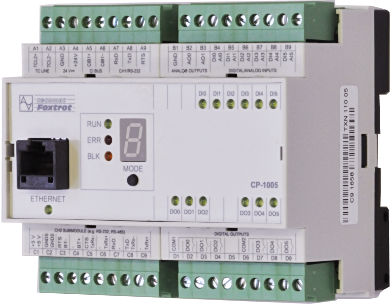
CP-1005TXN 110 05
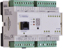
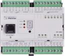
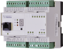
CP-1005, CPU, ETH100/10, 1xRS232, 1xSCH, 6xAI/DI, 2xAO, 6xRO 230 V/ 3A, 1xCIB
| DI | |
|---|---|
| DI/AI | 6x DI/AI |
| DO | 6x RO |
| AI | |
| AO | 2x AO |
| COM | |
| SENSOR |

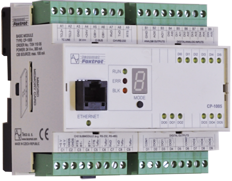
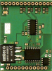
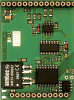
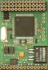
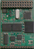
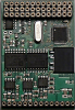
The basic module CP-1005 is equipped with six multi-purpose inputs, each of which can be used either as analog (voltage, current or for passive temperature sensors) or as binary 24V, two analog outputs 10V and 6 relay outputs. The CP-1005 basic module is equipped with a central unit (CPU) of the K series, which is designed for applications with high performance requirements. Includes backed up CMOS RAM for user programs, data, tables, user registers and DataBox, Flash memory for user program backup, MMC / SD / SDHC memory card slot, real time circuit, Ethernet interface, two serial channels (one with fixed interface RS-232, the other with a position for optional submodules), one communication channel with a CIB interface for connecting external peripherals and a TCL2 system interface designed for connecting expansion modules that increase the number of I / O systems.
| Order num. | TXN 110 05 |
|---|---|
| Teco code | TXN 110 05 |
| Categories | Foxtrot 1 - Basic modules |
| Tags | Sales and production discontinued |
| System parameters of the central unit | |
|---|---|
| Row of central unit | K |
| User program memory | 192 + 64 kB |
| Memory for user variables / including RETAIN variables | 64 kB/32 kB |
| Instruction length | 2 ÷ 10 bytes |
| Backup of program source code in PLC | Yes, in program backup memory (EEPROM) |
| On-line program change in PLC | Yes, including I / O configuration change |
| Memory for project archiving - internal | 2 MB |
| DataBox - additional internal data memory | 512 kB |
| Optional memory card slot | SD - Card Slot |
| Cycle time per 1k of logic instructions | 0,2 ms |
| Development environment | Mosaic |
| Programming languages | ST, IL, LD, FBD, SFC, CFC |
| RTC - Real time circuit | No |
| RAM and RTC backup 1) without / with backup battery | type. 500 hr / typ. 20,000 hours |
| Integrated Web server | Yes |
| Integrated Datalogger | Yes |
| Access to PLC variables via web API | Yes |
| Notice | 1) Applies to the basic module without power supply, the backup circuits are disconnected when the power supply is switched on 2) The serial interface CH1 is permanently equipped with an RS-485 interface. The serial interface type CH2 to CH4 is selectable via interchangeable submodules |
| COM - Communication - IP/Ethernet | |
| Ethernet 10/100 Mb (ETHx) | 1 |
| Available system modes on ETH and WLAN | UNI, PC, PLC, PLD |
| TCP / IP protocol | Yes |
| UDP protocol | No |
| HTTP protocol | No |
| WebSocket protocol | No |
| Protocol MODBUS/TCP | No |
| SMTP protocol | No |
| IEC 60870-5-104 protocol | No |
| REST API | No |
| COM - Serial channels | |
| max. number of optional serial channels in the basic module | 4 |
| max. number of expanding serial channels on the TCL2 bus | 6 |
| Number of internal RS-232 serial channels | 1 |
| Available system modes on CH5-10 | UNI, CSJ (CAN) |
| Modbus RTU / ASCII master protocol | No |
| Modbus protocol RTU/ASCII slave | No |
| Profibus DP master protocol (<180 kbit/s) | No |
| COM - System buses | |
| TCL2 - system I/O bus | 1x TCL2 master |
| TCL2 - Range of one branch of the system I/O bus | 10 I / O modules + 4 operator panels + 6 serial channels |
| The communication rate of the system I / O bus | 345 kbps |
| System I / O bus terminating resistor | 120 Ω |
| CIB - Common Installation Bus (R): Installation I/O bus | 1x CIB master (100 mA) |
| CIB - Address range of one branch of the installation bus | 32 CFox I/O modules |
| DI - Parameters of binary inputs DC (group A) | |
| Number of inputs in group | 6 |
| Common wire | minus |
| Input type | Type 1 (IEC) |
| Galvanic isolation of inputs from internal/peripheral circuits | No |
| Diagnostics | indication of energized input by LED on module panel |
| Pulse input overload capacity | max. 30 V (t < 10 ms) |
| Input voltage for log. 0 | 0 V DC; -5 V DC min.; +5 V DC max. |
| Input voltage for log. 1 | 24 V DC; 15 V DC min.; 30 V DC max. |
| Input current at log. 1 (typ.) | 5 mA typ. |
| Delay from log. 0 to log. 1 | 500 μs |
| Delay from log. 1 to log. 0 | 500 μs |
| The minimum width of the captured pulse | 500 μs |
| RO - Parameters of binary relay outputs (group A) | |
| Number of relay outputs | 6 |
| Number of output groups | 2 |
| Number of outputs in group | 3 |
| Diagnose | Alarm signaling on panel module |
| Switching current | 3 A max., 100 mA min. |
| Switching voltage | 250 V AC max., 5 V AC min., 30V DC max. |
| Short-term output overload - inrush | 4 A max. |
| Current through common clamp | 10 A max. |
| Contact closing time | typ. 10 ms |
| Contact opening time | typ. 4 ms |
| Limit values of switched resistive load | max. 3A at 30 V DC or 230 V AC |
| Switching inductive load limits DC13 | max. 3 A at 30 V DC |
| Switching inductive load limits AC15 | max. 3 A at 230 V AC |
| Switching frequency without load | max. 300 switching / min. |
| Switching frequency with rated load | max. 20 switching / min. |
| Mechanical life | min. 5,000,000 cycles |
| Electrical life at maximum resistive load | min. 100,000 cycles |
| Electrical life at maximum load inductive DC13 | min. 100,000 cycles |
| Electrical life at maximum load inductive AC15 | min. 100,000 cycles |
| Short-circuit protection | No |
| Treatment of inductive load | External RC element, varistor (AC), diode (DC) |
| Insulation voltage between outputs and internal circuits | 3750 V AC |
| Isolation voltage between groups of outputs to each other | 3750 V AC |
| AI - Organization of analog inputs | |
| Total number of analog inputs | 6 |
| Number of inputs per group | 6 |
| Number of analog input groups | 1 |
| Input type | With common clamp |
| Common wire | Minus |
| Galvanic separation from internal circuits | No |
| Diagnostics | overload signaling in status word |
| Digital resolution | 12 bit |
| Converter type | Approximation |
| conversion time | 20 μs |
| Analog input error - Temperature coefficient | ± 0,03% of full scale |
| Analog input error - Nonlinearity | ± 0.07% of full scale |
| Analog input error - Steady state repeatability | 0.05% of full scale |
| AI - Analog Input Ranges (Group A) | |
| Voltage | 0 to 10 V / 2,726 mV |
| Voltage | 0 to 5 V / 2,726 mV |
| Voltage | 0 to 2 V / 610.4 μV |
| Voltage | 0 to 1 V / 610.4 μV |
| Voltage | 0 to 0.5 V / 610.4 μV |
| Input impedance in the voltage signal range | > 20 kΩ |
| Permissible continuous overload - voltage input | -20 V to +30 V |
| Current | 4-20 mA |
| Permissible continuous overload - current input, resistance 100 R | ± 5 V / 50 mA max |
| Open input detection | No |
| Passive sensor | Pt100, W100=1,385 (-90 to +400 °C) |
| Passive sensor | Pt100, W100 = 1,391 (-90 to +400 °C) |
| Passive sensor | Pt1000, W100 = 1,385 (-90 to +400 °C) |
| Passive sensor | Pt1000, W100 = 1,391 (-90 to +400 °C) |
| Passive sensor | Ni1000, W100 = 1,500 (–60 to +200 ° C) |
| Passive sensor | Resistance transmitter 0-1 kOhm |
| AO - Analog output parameters | |
| Common wire of group | minus |
| Galvanic isolation from internal circuits | No |
| Output type | active voltage output |
| Diagnostics | None |
| Converter resolution | 12 bit |
| conversion time | 10 μs |
| Analog output error - maximum error at 25 ° C | ± 2% of full scale |
| Analog output error - temperature coefficient | ± 0.3% of full scale / K |
| Analog output error - linearity | ± 0.7% of full scale |
| Analog output error - repeatability under steady state conditions | ± 0.5% of full scale |
| Voltage output - voltage | 0 - 10,5 V |
| Voltage output - Resolution 1 LSB | 2,637 mV |
| Voltage output - maximum output current | 10 mA |
| Power supply | |
| Nominal supply voltage (V) | 24 V DC |
| Supply voltage, tolerances | 24 V DC, +25%, -15%, SELV |
| Supply voltage when backing up with an external battery | 27 V DC, +10%, –15%, SELV |
| Typical power input | 5 W |
| Maximum power input | 8 W |
| Module thermal/power loss | 6 W |
| Maximum current consumption (mA) | 400 mA |
| Galvanic separation of power supply from internal circuits | No |
| Internal protection | Yes, PTC reversible fuse |
| Description of power supply | Difference between typical and maximum power input is given by possible load of CIB buses and number of switched outputs and CPU load |
| CIB branch power supply - parameters of the built-in master | 1x 100 mA/ 24 V DC |
| Size and weight | |
| Weight approx. | 200 g |
| Product dimensions (width x height x depth) | 105 x 90 x 62 mm |
| Module width in multiples of M (17.5 mm) | 6M |
| Module width | 105 mm |
| Module height | 92 mm |
| Module depth | 63 mm |
| Product dimensions (width x height x depth) | 105 x 92 x 62 mm |
| Operating conditions, product standards | |
| Product standard | ČSN EN 61131-2: 2005 (idt IEC61131-2: 2003) - Programmable control units |
| Protection class of electrical object | II, according to ČSN EN 61140: 2003 (idt IEC 61140: 2001) |
| IP rating (Ingress Protection) according to ČSN EN 60529: 1993 (idt IEC 529: 1989) | IP20 |
| Operating areas | Normal, according to ČSN 33 2000-3: 1995 (mod IEC 364-3: 1993) |
| Degree of pollution | 1, according to ČSN EN 60664-1: 2004 (mod IEC 60664-1: 1992) |
| Overvoltage category installation | II, acc. ČSN EN 60664-1:2004 (mod IEC 606641:1992) |
| Type of device | Module on DIN rail |
| Working position | Vertical |
| Type of operation (operating frequency) | Continuous |
| Ambient operating temperatures | -20 °C to + 55 °C |
| Operating temperature maximum (° C) | +55°C |
| Operating temperature minimum (° C) | -20°C |
| Operating relative humidity | from 10 % up to 95 % without condensation |
| Operating atmospheric pressure | min. 70 kPa (<3,000 m above sea level) |
| Storage temperatures | –25 °C to +70 °C |
| Electromagnetic compatibility, Mechanical endurance | |
| Electromagnetic compatibility / Emission | A, according to EN 55022: 1999 (mod CISPR22: 1997) |
| Emmisions - note | In premises where the use of radio and television receivers can be expected to be used a distance of 10 m from these devices may cause radio interference. In such a case, the user may be required to take appropriate action. |
| Electromagnetic compatibility / Immunity | min. as required by EN 61131-2: 2007 |
| Sinusoidal vibration endurance | 10 Hz to 57 Hz, amplitude 0,075 mm, 57 Hz to 150 Hz, acceleration 1 G (Fc test according to EN 60068-2-6: 1997 (idt IEC 68-2-6: 1995), 10 cycles per axis.) |
| Packaginng, transportation, storage | |
| Description | The module is packed in a paper box. This documentation is also part of the package. The outer packaging is carried out according to the scope of the order and the method of transport in a transport package provided with labels and other data necessary for transport. The product must not be exposed to direct weather conditions during transport and storage. Malting of the product is only allowed in clean rooms without conductive dust, aggressive gases and vapors. The most suitable storage temperature is 20 ° C |
| Description |
The module is packed in a paper box according to the internal packing instructions. This documentation is also part of the package. The outer packaging is carried out according to the scope of the order and the method of transport in a transport package provided with transport labels and other data necessary for transport. Transport from the manufacturer is carried out in the manner agreed upon when ordering. The transport of the product by the customer's own means must be carried out by covered means of transport, in the position specified by the label on the packaging. The box must be stored in such a way that it does not move spontaneously and the outer packaging is not damaged. The product must not be exposed to direct weather conditions during transport and storage. Transport is permitted at temperatures of -25 ° C to +70 ° C, relative humidity of 10% to 95% (non-condensing) and a minimum atmospheric pressure higher than 70 kPa. The product may only be stored in clean rooms free of conductive dust, aggressive gases and vapors. The most suitable storage temperature is 20 ° C. |
| Installation | |
| Assembly description | Switchboard mounting |
| Assembly description | The basic module is mounted in a vertical position on the U-rail ČSN EN 50022. Installation of the assembly (basic module and possibly peripheral modules) is performed according to TXV 004 10 |
| Exchangeable submodules | The optional MR-01xx submodules with serial channel 2 interface are mounted on the center plate in the CP-10x0 basic module to the position indicated in Fig. 7.1. To add or replace a submodule with a serial channel interface, release the latches on |
| Module operation | |
| Commissioning | The module is ready for operation after connecting the supply voltage. The MODE button is available on the module panel to display the currently set Ethernet IP address. The parameters of all interfaces are set in the Mosaic development environment. |
| Module diagnostics | The basic diagnostic system of the module is a part of its standard software. It operates from module power on and operates independently of the user. Diagnostic error states of the module and connected peripheral modules of the assembly are signaled |
HW documentation
CP-1005 Basic documentation
684.58 kB
CP-1005/1015 User's Guide
5.20 MB
User manuals
Foxtrot1 - User's Guide, cze, , TXV00410_01
3.40 MB
Foxtrot1 - User Manual (en), TXV00410_02
4.30 MB
Files for designers
CP-1005 technical drawing DWG
137.72 kB
CP-1005 technical drawing DXF
391.35 kB
MR-0124
TXN 101 24
MR-0124, RS-422, with its own power supply and auto-identification, galvanic isolation
MR-0160
TXN 101 60
MR-0160, 2x CAN (SJA1000, Philips), with its own power supply, galvanic isolation
MR-0105
TXN 101 05
MR-0105, 1x RS-485, 2x RS-232 (FOXTROT only), GO with its own power supply and auto-identification
MR-0106
TXN 101 06
MR-0106, 2x RS-485, 1x RS-232 (FOXTROT only), with its own power supply and auto-identification, galvanic isolation

MR-0161
TXN 101 61
MR-0161, 1x CAN (SJA1000, Philips), with its own power supply, galvanic isolation
MR-0115
TXN 101 15
MR-0115, 3x RS-485, (FOXTROT only), with its own power supply and auto-identification, galvanic isolation
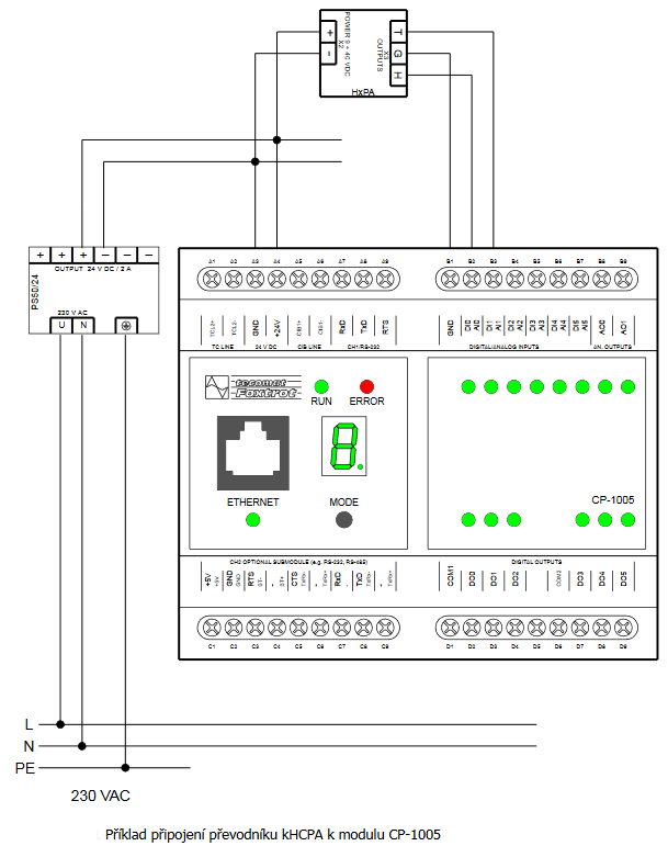
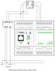
- Connecting two-wire sensors 4 ÷ 20 mA to CP-1005 - ...onnection of two current sensors 4 to 20 mA in a two-wire version. In the same way up to six sensors can be connected to one CP-1005 module. The 24 V power supply can be a separate device, or a common power supply can be used for powering of both the...
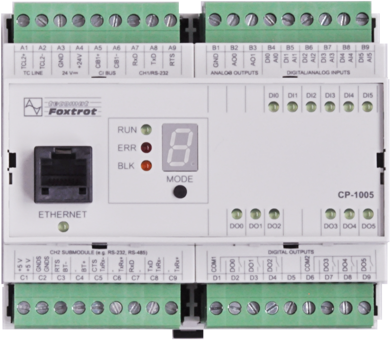
- CP-1005 - The CP-1005 is the basic module of the Foxtrot control system. A standard configuration of the module is in a 6M housing on a DIN rail (for the housing dimensions, see Chapter 6M housing on a DIN rail ), and it is fitted with six removable termina...
- Power dissipation of modules for calculation of switchboard heating - ...2, 1xSCH, 4xDI/AI, 4xDI/HSC, 6xRO 230 V/ 3A,1xCIB CP-1004 5,0 W TXN 110 05 CP-1005, CPU, ETH100/10, 1xRS232, 1xSCH, 6xAI/DI, 2xAO, 6xRO 230 V/ 3A, 1xCIB CP-1005 5,0 W...
- Internal CIB master at the CP-10xx - ...CP-1004, CP-1014 100 mA 1 A (module C-BS-0001M ) CP-1005, CP-1015 100 mA 1 A (module C-BS-0001M )...
- CP-1015 - The CP-1015 I/O layout (inputs, outputs, power supply, communication interface) is identical with the CP-1005 module. The front panel is different: instead of LED indicators and a small seven-segment indicator there is a larger display with...
- Foxtrot basic module power supply - ...CP-1004, CP-1014 8 W 4 W CP-1005, CP-1015 8 W 4 W CP-1006, CP-1016...
- The 5A relays, the Foxtrot basic modules and the peripheral CFox modules - These relays are fitted in e.g. the Foxtrot basic modules (CP-1005, CP1006, etc.), the peripheral modules ( C-HM-0308M , C-IR-0202S ) and others (see information on the individual modules ). The parameters of t...
- RH and temperature measurement for HVAC applications, the sensor with a 4÷20 mA output - ...uced by Sensorika ) see the following figure below. Fig. 1. An example of wiring the kHCPA converter to the CP-1005 module Notes: The converter is equipped with active current outputs with a common minus terminal....
- Foxtrot 2 - Shifts to two! - ...the CP-2005, which with six universal digital / analog inputs, six relay and two analog outputs corresponds to the existing CP-1005 with the aim of replacing it 1: 1. Another variant in this dimension is the CP-2080 with a new combination of four co...
- First generation Tecomat Foxtrot PLC - ..., Provedení: DIN-RAIL, Interface: Multi, Bus: TC700, Input: true, Output: true, Analog: true, Binary: true ] CP-1005 CP-1005-Základní modul Foxtrot [ AO: 2, DO: 6, Typ: PLC-Foxtrot, Výrobce: Teco, Provedení: DIN-RAIL, Interfa...
- MR-0105, MR-0106, MR-0115, fitted with the CP-10x4, CP-10x5 - Tab. 1: Terminating of the CH2, CH3 and CH4 communication channels for the CP-10x4 , CP-10x5 Terminal block C Terminal MR-0105...
- The FOXTROT basic modules - The CP-10xx analogue inputs, ranges, basic information The analogue inputs in basic modules make it possible to connect a number of sensors and measured signals. Each CP-10xx variant is fitted with various numbers of inputs with different para...
- Connecting an electricity meter via the TXN 149 01 optical head - The TXN 149 01 optical interface probe (also called an optical head) is designed to read data and to communicate with the electricity meter, the ripple control receiver and other devices. The probe converts optical signals into signals of the serial...
- CP1005. cannot connect to it via Ethernet cable - Error A0-03-4301 means that the peripheral module in the CP-1005 unit has stopped communicating with the processor. This can be caused either by a fault on the module or by interference that can enter the system either through the power supply or th...
- Technical documentation - ...these control units are not already produced and the original manual for them was only in Czech language. Similar system is CP-1005 and its manual is here (English version). The manual for CP-1006 in the Czech language version is here I am very...