 English
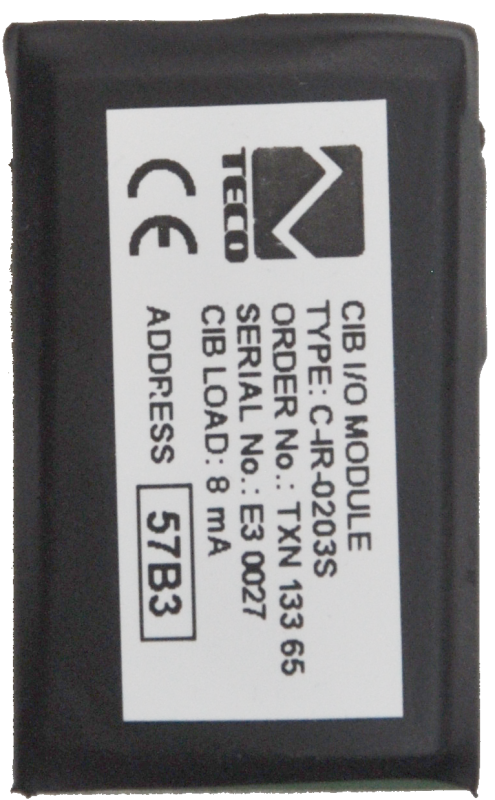


C-IR-0203STXN 133 65
C-IR-0203S; CIB, 2x AI / DI Temperature / contact, 2x AO (0-10V); 1x RO, 230V / 16A (inrush 80A) make / break contact
| DI | 2x DI/AI |
|---|---|
| DO | |
| AI | 2x DI / AI see DI |
| AO | 2x AO |
| COM | 1x CIB slave |
| SENSOR |
| Picture | Variant | Variant description |
|---|---|---|

|
C-IR-0203S-16A | Output current: 16 A |

|
C-IR-0203S-5A | Output current: 5 A |

|
C-IR-0203S | Production and sales: discontinued |
C-IR-0203S is a module designed for connection to the CIB bus. Contains
- two combined analog or binary inputs
- two analog outputs with a range of 0-10 V
- one relay output with changeover contact.
Inputs and analog outputs are connected to the terminal block with pen terminals, the relay output to the terminal block with screw cage terminals.
- The inputs allow direct connection of resistance sensors PT1000, Ni1000, sensor with thermistor NTC12k or KTY81-121 against a common GND wire. The resistance is converted in the module directly to a numerical temperature value.
- For another type of resistance sensor, resistance measurement in the range 0-160 kΩ can be selected, but the conversion to temperature and linearization must be performed only at the level of the user program.
- The binary signals are connected to the inputs only as a free potential-free contact against the common conductor GND, or the input can operate in balanced input mode.
- The 0-10 V analog outputs are connected to a common GND conductor.
| Order num. | TXN 133 65 |
|---|---|
| Teco code | TXN 133 65 |
| Categories | CFox - Built-in modules |
| Tags | - |
| COM - System buses | |
|---|---|
| CIB - Common Installation Bus (R): Installation I/O bus | 1x CIB slave |
| RO - Parameters of binary relay outputs (group A) | |
| Parameters valid for the terminals | DO1 |
| Number of relay outputs | 1 |
| Output type | electromechanical relay, unprotected output |
| Contact type | NO / NC changeover contact |
| Galvanic separation from internal circuits | Yes |
| Diagnose | Alarm signaling on panel module |
| Switching current | 16 A max., 100 mA min. |
| Switching voltage | 300 V max., 5 V min. |
| Contact closing time | typ. 15 ms |
| Contact opening time | typ. 5ms |
| Short-circuit protection | No |
| Insulation voltage between outputs and internal circuits | 3750 V AC |
| AI - Organization of analog inputs | |
| Total number of analog inputs | 2 |
| Number of inputs per group | 2 |
| Number of analog input groups | 1 |
| Input type | With common clamp |
| Common wire | Minus |
| Galvanic separation from internal circuits | No |
| Diagnostics | overload signaling in status word |
| AO - Analog output parameters | |
| The number of groups of analogue outputs | 1 |
| Common wire of group | minus |
| Galvanic isolation from internal circuits | No |
| Output type | active voltage output |
| Operating conditions, product standards | |
| Product standard | ČSN EN 60730-1 ed. 2:2001 (mod IEC 60730-1:1999) |
| Protection class of electrical object | II, according to ČSN EN 61140 ed.3: 2016 (idt IEC 61140:2016) |
| IP rating (Ingress Protection) according to ČSN EN 60529: 1993 (idt IEC 529: 1989) | IP10B |
| Operating areas | Normal, acc. ČSN 33 2000-1 ed.2: 2009 (mod IEC 60354-1:2005) |
| Degree of pollution | 1, according to ČSN EN 60664-1 ed.2:2008 ( idt IEC 60664-1:2007) |
| Overvoltage category installation | I, according to ČSN EN 60664-1 ed_2:2008 (idt IEC 60641-1:2007) |
| Type of device | In the installation box, under the cover |
| Working position | Any |
| Type of operation (operating frequency) | Continuous |
| Ambient operating temperatures | -10 °C to + 55 °C |
| Storage temperatures | –25 ° C to + 85 ° C |
| Electromagnetic compatibility, Mechanical endurance | |
| Electromagnetic compatibility / Emission | ČSN EN 55022 ed2:2007 (mod CISPR22:2005) |
| Electromagnetic compatibility / Immunity | min. according to ČSN EN 60730-1 ed.2: 2001 |
| Sinusoidal vibration endurance | 10 Hz to 57 Hz, amplitude 0,075 mm, 57 Hz to 150 Hz, acceleration 1 G (Fc test according to EN 60068-2-6: 1997 (idt IEC 68-2-6: 1995), 10 cycles per axis.) |
| Packaginng, transportation, storage | |
| Description | The module is packed in a paper box. This documentation is also part of the package. The outer packaging is carried out according to the scope of the order and the method of transport in a transport package provided with labels and other data necessary for transport. The product must not be exposed to direct weather conditions during transport and storage. Malting of the product is only allowed in clean rooms without conductive dust, aggressive gases and vapors. The most suitable storage temperature is 20 ° C |
| Connection | |
| Connection of power and system communication | terminal block with spring clamp 1 mm2, push-in |
| Connection of inputs / outputs | terminal block with spring clamp 1 mm2, push-in |
| Specific I / O | Relay output |
| Connection of specific I / O | terminal block with screw terminal 1.5 mm2 |
| Module operation | |
| Commissioning | The module is operated, set and diagnosed from the MOSAIC programming environment or other parameterization software. The module is ready for operation after connecting the supply voltage and the CIB bus. The HW address is indicated on the label on the module. |
| Module diagnostics | The basic diagnostics is performed internally and the result is available in the relevant registers of the Mosaic environment. |
| Maintenance | |
| Description | The module does not require any maintenance under general installation conditions. The operations in which a part of the module has to be dismantled must always be carried out with the supply voltage disconnected. |
| Notice | Because the module contains semiconductor components, it is necessary to follow the principles for working with electrostatic sensitive components when handling the removed cover. It is not allowed to directly touch the printed circuit boards without protective measures !!! |
| Warranty | |
| Generally | Warranty and complaint conditions are governed by the Terms and Conditions of Teco a.s. |
| Notice | You must meet all the conditions of this documentation before turning on the system. The system must not be put into service unless it has been verified and confirmed that the machinery meets the requirements of Directive 89/392 / EEC, in so far as it applies to it. Documentation subject to change. |
HW documentation
C-IR-0203S - Basic documentation
873.45 kB, (EN)
User manuals
Peripheral modules on the CIB Common Installation Bus(R) (en), TXV00413_02
13.94 MB, (EN, RU, DE, UA)
Files for designers
Foxtrot 2 - library of elements in DXF and DWG formats, v. 2025/05.
20.59 MB
Foxtrot 2 - element library for SchemataCAD, v. 2025/05.
6.92 MB
EC - Declaration of Conformity
Foxtrot - EC Declaration of conformity
295.20 kB, (EN, RU, DE, UA)
- C-IR-0203S - The C-IR-0203S module is designed to connect two temperature sensors or binary signals, controlled by the power relay contact; it is fitted with two analogue outputs directly on the CIB bus. The PT1000 or Ni1000 resistance sensors can be connecte...
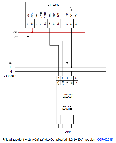
- HELVAR ballast control by C-IR-0203S module - To control the HELVAR electronic ballasts (and similar types of other manufacturers) designed to dim fluorescent lamps controllable by analog voltage 0 ÷ 10 V or 1 ÷ 10 V, it is possible to use e.g. the C-IR-020 3S module,...
- Switching of LED lighting, light bulbs, fluorescent lamps, etc. - ...h short-term switching current up to 800 A C-HM-1121M 3 relay outputs with short-term switching current up to 800 A C-IR-0203S 1 relay output with short-term switching current up to 80 A R-OR-0001B 1 relay output with short-term switch...
- 0 ÷ 10 V ballast control by C-IR-0202S module - For controlling the electronic ballasts of fluorescent lights controllable by analog voltage 0 ÷ 10 V or 1 ÷ 10 V e.g. the C-IR-0202S module can be used, which is equipped with a relay output for switching off the ballast...
No data available.