

C-HM-1121MTXN 133 11
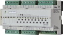
C-HM-1121M; CIB, 3x AI, 8x DI, 2x AO, 16x RO/5A, 3x RO/16A
| DI | 8x DI |
|---|---|
| DI/AI | |
| DO | 16x RO (5 A) 3x RO (16 A) |
| AI | 3x AI |
| AO | 2x AO |
| COM | 1x CIB slave |
| SENSOR |
| Picture | Variant | Variant description |
|---|---|---|

|
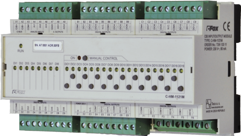
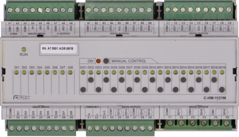
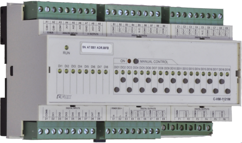
C-HM-1121M |
Module with a total of 32 inputs and outputs of digital, analog and relay in combination suitable to cover the needs of a typical hotel room or similar spaces.
It is connected to the basic module via the two-wire CIB Common installation BUS for communication.
The power supply is from the 230 V AC network to cover a higher consumption of a large number of inputs and especially relay outputs.
The module has 3 relays with a high permanent load capacity of 16A and resistance to inrush currents typical of switched power supplies and so-called electronic transformers or LED bulbs.
Other relays are low power suitable for loads of resistive or inductive nature.
Each digital input and real output has a separate indication of use and switching by LED on the front panel.
The module can be switched to manual (service) mode and each output can be controlled separately with the buttons on the front panel.
Use:
Sensing the state of contacts, resistance sensors
Switching and opening by contact in general.
3 of the 19 relay outputs have increased resistance to inrush current of switching power supplies up to 165A.
Suitable for switching LED bulbs, ballasts and capacitive transformers
Continuous control of other devices with analog signal 0-10V
| Order num. | TXN 133 11 |
|---|---|
| Teco code | TXN 133 11 |
| Categories | CFox - Modules on DIN rail |
| Tags | Power supply 230V |
| COM - System buses | |
|---|---|
| CIB - Common Installation Bus (R): Installation I/O bus | 1x CIB slave |
| DI - Organization of binary inputs | |
| Total number of binary inputs | 8 |
| Number of groups of binary inputs | 1 |
| Organization of binary inputs into groups | 8x (DI1- DI8) |
| DI - Parameters of binary inputs DC (group A) | |
| Parameters valid for inputs on the terminals | DI1- DI8 |
| Number of inputs in group | 8 |
| Common wire | COM |
| Input type | active (for dry contacts connection) |
| Combined input type | DI - Binary, balanced |
| Galvanic isolation of inputs from internal/peripheral circuits | No |
| Diagnostics | signaling of the excited LED input on the module panel and in the Mosiac programming environment |
| Input current at log. 1 (typ.) | 1,5 mA typ. |
| Delay from log. 0 to log. 1 | 500 μs |
| The minimum width of the captured pulse | 50 μs |
| Notice | ATTENTION, the common terminal of binary inputs DI1 ÷ DI8 is with a positive voltage of 2.5 V against the common GND terminal of the module |
| DO/RO - Organization of binary outputs | |
| Total number of binary outputs | 18 |
| Number of binary output groups | 6 |
| RO - Parameters of binary relay outputs (group A) | |
| Number of relay outputs | 16 |
| Organization of relay outputs into groups | 3 (DO1-3)+3 (DO4-6)+3 (DO7-9)+3 (DO10-12)+2 (DO13-14)+2 (DO15-16) |
| Output type | electromechanical relay, unprotected output |
| Contact type | NO - Normally Open |
| Diagnose | Alarm signaling on panel module |
| Switching current | 3 A max., 10 mA min. |
| Switching voltage | 250 V AC max., 5 V AC min., 30V DC max. |
| Short-term output overload - inrush | 5 A max. (20 ms max.) |
| Current through common clamp | 10 A max. |
| Contact closing time | typ. 10 ms |
| Contact opening time | typ. 10 ms |
| Switching frequency without load | max. 120 switchings / min. |
| Switching frequency with rated load | max. 30 switchings / min |
| Mechanical life | min. 5,000,000 cycles |
| Electrical life at maximum resistive load | min. 200,000 cycles |
| Short-circuit protection | No |
| Treatment of inductive load | External RC element, varistor (AC), diode (DC) |
| Insulation voltage between outputs and internal circuits | 4000 V AC |
| Isolation voltage between groups of outputs to each other | 4000 V AC |
| Insulation voltage between contacts | 750 V AC |
| RO - Parameters of binary relay outputs (group B) | |
| Number of relay outputs | 3 |
| Number of output groups | 3 |
| Number of outputs in group | 1 |
| Output type | electromechanical relay, unprotected output |
| Contact type | NO - Normally Open |
| Diagnose | Alarm signaling on panel module |
| Switching current | 16 A max., 100 mA min. |
| Switching voltage | max. 250 V AC; max. 30 V DC; min. 5 V |
| Short-circuit protection | No |
| Short-term output overload | 165 A max. (20 ms max.) |
| Contact closing time | typ. 10 ms |
| Contact opening time | typ. 10 ms |
| Switching frequency without load | max. 60 sepnutí/min. |
| Switching frequency with rated load | max. 6 switching / min |
| Mechanical life | min. 5,000,000 cycles |
| Electrical life at maximum resistive load | min. 40,000 cycles |
| Treatment of inductive load | External RC element, varistor (AC), diode (DC) |
| Insulation voltage between outputs and internal circuits | 4000 V AC |
| Isolation voltage between groups of outputs to each other | 4000 V AC |
| Insulation voltage between contacts | 1250 V AC |
| AI - Organization of analog inputs | |
| Total number of analog inputs | 3 |
| Number of analog input groups | 1 |
| Organization of analog inputs into groups | 3x (AI1-AI3) |
| Input type | With common clamp |
| Common wire | Plus |
| External power supply | No |
| Digital resolution | 12 bit |
| Converter type | Approximation |
| conversion time | 500 μs |
| Analog input error - Temperature coefficient | ± 0,1% of full scale/K |
| Analog input error - Steady state repeatability | ± 0,5% of full scale |
| AI - Analog Input Ranges (Group A) | |
| Parameters valid for inputs on the terminals | AI1-AI3 |
| Passive sensor | Pt1000, W100 = 1,385 (-90 to +320 °C) |
| Passive sensor | Pt1000, W100 = 1,391 (-90 to +320 °C) |
| Passive sensor | Ni1000, W100 = 1,500 (–60 to +200 ° C) |
| Passive sensor | Ni1000, W100 = 1.617 (-60 to +200 ° C) |
| Passive sensor | Resistance transmitter 0-600 kOhm |
| Passive sensor | Resistance transmitter 0-6 MOhm |
| Passive sensor | KTY81-121; PTC thermistor (-55 to + 125 °C) |
| Passive sensor | NTC Thermistor 12k / 25 °C (-40 to + 125 °C) |
| Resistance measurement error - maximum error at 25 ° C | ± 2% of full scale |
| AO - Analog output parameters | |
| Parameters valid for the terminals | AO1-AO2 |
| Common wire of group | minus |
| Galvanic isolation from internal circuits | No |
| Output type | active voltage output |
| Converter resolution | 8 bit |
| Analog output error - temperature coefficient | ± 0.3% of full scale / K |
| Analog output error - linearity | ± 0.7% of full scale |
| Voltage output - voltage | 0 - 10,5 V |
| Voltage output - Resolution 1 LSB | 41 mV |
| Voltage output - maximum output current | 10 mA |
| Power supply | |
| Module thermal/power loss | 7 W |
| Size and weight | |
| Weight approx. | 450 g |
| Product dimensions (width x height x depth) | 158 x 90 x 58 mm |
| Operating conditions, product standards | |
| Product standard | ČSN EN 60730-1 ed. 3:2012 (mod IEC 60730-1:2010) |
| Protection class of electrical object | I, according to ČSN EN 61140 ed.3: 2016 (idt IEC 61140:2016) |
| IP rating (Ingress Protection) according to ČSN EN 60529: 1993 (idt IEC 529: 1989) | IP10B |
| Operating areas | Normal, acc. ČSN 33 2000-1 ed.2: 2009 (mod IEC 60354-1:2005) |
| Degree of pollution | 1, according to ČSN EN 60664-1 ed.2:2008 ( idt IEC 60664-1:2007) |
| Overvoltage category installation | II, according to EN 60664-1 ed_2: 2008 (idt IEC 60641-1: 2007) |
| Type of device | Module on DIN rail |
| Working position | Vertical |
| Type of operation (operating frequency) | Continuous |
| Ambient operating temperatures | -10 °C to + 55 °C |
| Operating relative humidity | from 10 % up to 95 % without condensation |
| Operating atmospheric pressure | min. 70 kPa (<3,000 m above sea level) |
| Storage temperatures | –25 °C to +70 °C |
| Electromagnetic compatibility, Mechanical endurance | |
| Electromagnetic compatibility / Emission | B, according to EN 55032 ed. 2: 2017 (idt CISPR 32: 2015) |
| Electromagnetic compatibility / Immunity | min. according to ČSN EN 60730-1 ed.2: 2001 |
| Sinusoidal vibration endurance | 10 Hz to 57 Hz, amplitude 0,075 mm, 57 Hz to 150 Hz, acceleration 1 G (Fc test according to EN 60068-2-6: 1997 (idt IEC 68-2-6: 1995), 10 cycles per axis.) |
| Packaginng, transportation, storage | |
| Description | The module is packed in a paper box. This documentation is also part of the package. The outer packaging is carried out according to the scope of the order and the method of transport in a transport package provided with labels and other data necessary for transport. The product must not be exposed to direct weather conditions during transport and storage. Malting of the product is only allowed in clean rooms without conductive dust, aggressive gases and vapors. The most suitable storage temperature is 20 ° C |
| Installation | |
| Assembly description |
Das kombinierte Modul C-HM-1121M ist vertikal auf der U-Schiene ČSN EN 50022 montiert. Die Installation der Baugruppe (Basismodul und möglicherweise Peripheriemodule) erfolgt gemäß TXV 004 13. |
| Connection | |
| Connection of power and system communication | connector with 2.5 mm2 screw terminal |
| Connection of inputs / outputs | connector with screw terminal 2.5 mm2 |
| Specific I / O | F1-F6 |
| Connection of specific I / O | Terminal block, max. 4 mm2 conductors |
| Module operation | |
| Commissioning | The module is ready for operation after connecting the supply voltage. The MODE button is available on the module panel to display the currently set Ethernet IP address. The parameters of all interfaces are set in the Mosaic development environment. |
| Module diagnostics | The basic diagnostic system of the module is a part of its standard software. It operates from module power on and operates independently of the user. Diagnostic error states of the module and connected peripheral modules of the assembly are signaled |
| Maintenance | |
| Description | The module does not require any maintenance under general installation conditions. The operations in which a part of the module has to be dismantled must always be carried out with the supply voltage disconnected. |
| Notice | Because the module contains semiconductor components, it is necessary to follow the principles for working with electrostatic sensitive components when handling the removed cover. It is not allowed to directly touch the printed circuit boards without protective measures !!! |
| Warranty | |
| Generally | Warranty and complaint conditions are governed by the Terms and Conditions of Teco a.s. |
| Notice | You must meet all the conditions of this documentation before turning on the system. The system must not be put into service unless it has been verified and confirmed that the machinery meets the requirements of Directive 89/392 / EEC, in so far as it applies to it. Documentation subject to change. |
HW documentation
C-HM-1121M - Basic documentation
938.76 kB, (EN)
User manuals
Peripheral module on CIB-Common Installation Bus(R) (cs), TXV00413_01
14.01 MB
Peripheral modules on the CIB Common Installation Bus(R) (en), TXV00413_02
13.94 MB, (EN, RU, DE, UA)
EC - Declaration of Conformity
Foxtrot - EC Declaration of conformity
295.20 kB, (EN, RU, DE, UA)
Files for designers
Foxtrot 2 - library of elements in DXF and DWG formats, v. 2025/08.
21.80 MB
Foxtrot 2 - element library for SchemataCAD, v. 2025/08.
6.96 MB
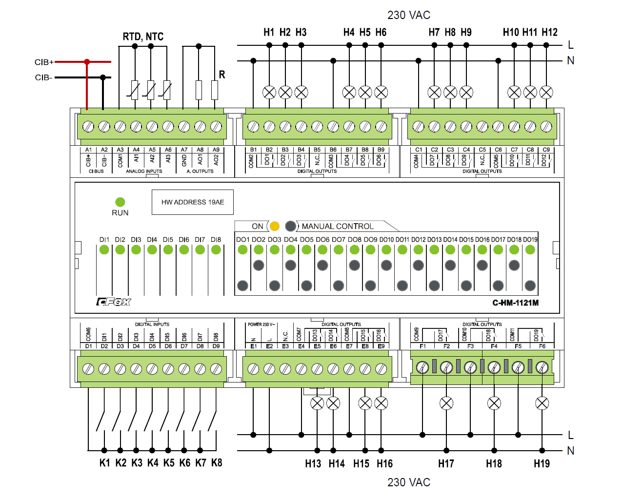
- C-HM-1121M - An example of connection and the conditions of the module usage: Fig. 1 The basic connection of the C-HM-1121M module Notes: The DI1 to DI8 inputs are intended only for connecting potenti...
- Power dissipation of modules for calculation of switchboard heating - ...CIB, 3x AI, 8x DI, 2x AO, 10x RO/5A, 1xRO/16A C-HM-1113M 3,5 W TXN 133 11 C-HM-1121M; CIB, 3x AI, 8x DI, 2x AO, 16x RO/5A, 3x RO/16A C-HM-1121M 7,0 W TXN 133...
- CIB power supply – principles, optimization - ...oad (take-off from power supply). Most peripheral modules are powered from CIB. However, there are modules, e.g. the C-HM-1121M , which are powered from 230VAC, or the C-OR-0008M , C-OR-0011M-800 , C-JC-0006M and C-IB-180...
- 16 A relay (160 A switching current), the CFox and RFox peripheral modules - These relays are fitted in e.g. the C-OR-0011M-800 , C-LC-0202B , C-HM-1121M , R-HM-1121M peripheral modules, and others (see the information on the individual modules ). Tab. 1. The parameters of the actual relay cont...
- R-HM-1121M - The module is no longer for sale The R-HM-1121M module is functionally fully consistent with the C-HM-1121M module (the inputs, outputs). The only difference is in communication. The module is in a wireless version – a pe...
- Measurements of dewing (condensation of air humidity) - ...he AI5 input of the C-AM-0600I module, or to the inputs AI1 to AI3 of the modules C-HM-0308M , HM-C-1113M and C-HM-1121M . In order for the dew sensor to function properly, it must have the same temperature as the surfa...
- The push-buttons scanned by the C-IB-1113M module in the control panel - ...tions with assumed placement of the control system modules in the control panel can also use the C-HM-1113M and the C-HM-1121M modules. They should be placed in the main control panel (together with the basic module) or in subordinate dis...
- Control of socket circuits and sockets - ...relay outputs located in the switchboard (typically C-OR-0008M , C-OR-0011M-800 modules, 16 A outputs of the C-HM-1121M module and their RFox variants), see this article placed in the installation box C-OR-0202B a...
- Switching a common source with independent control of several LED strips - ...rce (to avoid permanent power consumption when the lighting is switched off), it is recommended to use the C-HM-1113M (or C-HM-1121M ) modules: to switch the source, the 16 A output can be used (DO11, this output is designated for switching curre...
- Switching of LED lighting, light bulbs, fluorescent lamps, etc. - ...ith short-term switching current up to 80 A C-HM-1113M 1 relay output with short-term switching current up to 800 A C-HM-1121M 3 relay outputs with short-term switching current up to 800 A C-IR-0203S 1 relay output with short-term swit...
- The separate temperature sensor S-TS-01R, connected to the AI of the system - The interior temperature can be measured with the S-TS-01R stand-alone temperature sensor (e.g. the NTC 12k) designed according to the customer's requirements. The sensor is available in ABB Time design under the order number TXN 134 01.01 (ba...
- The push-buttons scanned by the C-IB-1800M module in the control panel - Installations with assumed placement of the control system modules in the control panel require the C-IB-1800 module. It should be placed in the main control panel (together with the basic module) or in subordinate distribution boards (in ord...
No data available.