


C-HM-1113MTXN 133 10
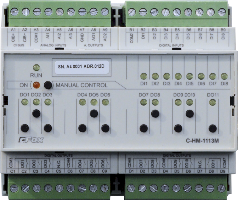
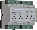
C-HM-1113M; CIB, 3x AI, 8x DI, 2x AO, 10x RO/5A, 1xRO/16A
| DI | 8x DI |
|---|---|
| DI/AI | |
| DO | 11x RO |
| AI | 3x AI |
| AO | 2x AO (0-10V) |
| COM | 1x CIB slave |
| SENSOR |
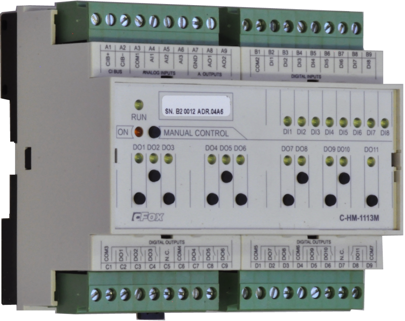
| Picture | Variant | Variant description |
|---|---|---|

|
C-HM-1113M |
The C-HM-1113M modules are designed for connection to the CIB bus. The module contains
- 8 binary inputs for contacts
- 3 analog inputs with common terminal
- 2 analog outputs with common terminal
- 11 relay outputs grouped
The outputs can be switched manually after switching to manual mode. The analog inputs are configurable according to the type of resistance sensor used, supplied from a common terminal.
Analog outputs are with 8 bit resolution, voltage 0 ÷ 10V.
The module is equipped with removable screw connectors.
| Order num. | TXN 133 10 |
|---|---|
| Teco code | TXN 133 10 |
| Categories | CFox - Modules on DIN rail |
| Tags | - |
| COM - System buses | |
|---|---|
| CIB - Common Installation Bus (R): Installation I/O bus | 1x CIB slave |
| DI - Organization of binary inputs | |
| Total number of binary inputs | 8 |
| Number of groups of binary inputs | 1 |
| DI - Parameters of binary inputs DC (group A) | |
| Parameters valid for inputs on the terminals | DI1 - DI8 |
| Number of inputs in group | 8 |
| Common wire | COM2 |
| Combined input type | DI/AI Active, for sensing potential-free contacts and measuring resistance sensors |
| Galvanic isolation of inputs from internal/peripheral circuits | No |
| Diagnostics | indication of energized input by LED on module panel |
| Input voltage for log. 0 | 0,25*VDI max. |
| DO/RO - Organization of binary outputs | |
| Total number of binary outputs | 11 |
| Number of binary output groups | 5 |
| RO - Parameters of binary relay outputs (group A) | |
| Number of relay outputs | 10 |
| Number of output groups | 4 |
| Organization of relay outputs into groups | 3x (DO1-DO3)+3x (DO4-DO6)+ 2x (DO7-8) + 2x (DO9-10) + 1x (DO11) |
| Output type | electromechanical relay, unprotected output |
| Contact type | NO - Normally Open |
| Diagnose | Alarm signaling on panel module |
| Switching current | 3 A max., 100 mA min. |
| Switching voltage | 250 V AC max., 5 V AC min., 30V DC max. |
| Short-term output overload - inrush | 4 A max. |
| Current through common clamp | 10 A max. |
| Contact closing time | typ. 10 ms |
| Contact opening time | typ. 4 ms |
| Switching inductive load limits DC13 | max. 3 A at 30 V DC |
| Switching inductive load limits AC15 | max. 3 A at 230 V AC |
| Switching frequency without load | max. 300 switching / min. |
| Switching frequency with rated load | max. 20 switching / min. |
| Mechanical life | min. 5,000,000 cycles |
| Electrical life at maximum resistive load | min. 100,000 cycles |
| Electrical life at maximum load inductive DC13 | min. 100,000 cycles |
| Electrical life at maximum load inductive AC15 | min. 100,000 cycles |
| Short-circuit protection | No |
| Treatment of inductive load | External RC element, varistor (AC), diode (DC) |
| RO - Parameters of binary relay outputs (group B) | |
| Number of relay outputs | 1 |
| Number of output groups | 1 |
| Number of outputs in group | 1 |
| Organization of relay outputs into groups | DO11 |
| Output type | electromechanical relay, unprotected output |
| Contact type | NO - Normally Open |
| Diagnose | Alarm signaling on panel module |
| Switching current | 10 A max., 100 mA min. |
| Switching voltage | max. 250 V AC; max. 30 V DC; min. 5 V |
| Short-circuit protection | No |
| AI - Organization of analog inputs | |
| Total number of analog inputs | 2 |
| Number of inputs per group | 2 |
| Number of analog input groups | 1 |
| Input type | With common clamp |
| Common wire | Plus |
| Galvanic separation from internal circuits | No |
| Diagnostics | overload signaling in status word |
| Digital resolution | 12 bit |
| Analog input error - Temperature coefficient | ± 0,1% of full scale/K |
| Analog input error - Nonlinearity | ± 0,1% of full scale |
| Analog input error - Steady state repeatability | ± 0,5% of full scale |
| AI - Analog Input Ranges (Group A) | |
| Passive sensor | Pt1000, W100 = 1,385 (-90 to +320 °C) |
| Passive sensor | Pt1000, W100 = 1,391 (-90 to +320 °C) |
| Passive sensor | Ni1000, W100 = 1,500 (–60 to +200 ° C) |
| Passive sensor | Ni1000, W100 = 1.617 (-60 to +200 ° C) |
| Passive sensor | Resistance transmitter 0-600 kOhm |
| Passive sensor | Resistance transmitter 0-6 MOhm |
| Passive sensor | KTY81-121; PTC thermistor (-55 to + 125 °C) |
| Passive sensor | NTC Thermistor 12k / 25 °C (-40 to + 125 °C) |
| DI: Voltage-free contact | 0 when> 1.5 kOhm, 1 when <0.5 kOhm |
| Resistance measurement error - maximum error at 25 ° C | ± 0.5% of full scale, ± 10% of range (0-200 kOhm) |
| Resistance measurement error - temperature coefficient | ± 0.05% of full scale / K |
| Resistance measurement error - non-linearity | ± 0.09% of full scale |
| Resistance measurement error - repeatability at steady conditions | 0.07% of full scale |
| AO - Analog output parameters | |
| The number of groups of analogue outputs | 1 |
| Number of outputs and their organization into groups | 2x (AO1, AO2) |
| Parameters valid for the terminals | AO1, AO2 |
| Common wire of group | GND terminal |
| Galvanic isolation from internal circuits | No |
| Output type | active voltage output |
| Type of protection | No |
| Converter resolution | 8 bit |
| conversion time | 10 μs |
| Analog output error - maximum error at 25 ° C | ± 0.3% of full scale |
| Analog output error - temperature coefficient | ± 0.05% of full scale/K |
| Analog output error - linearity | ± 0.1% of full scale |
| Analog output error - repeatability under steady state conditions | ± 0.5% of full scale |
| Voltage output - maximum output current | 10 mA |
| Power supply | |
| Nominal supply voltage (V) | 24 V DC |
| Module thermal/power loss | 3,5 W |
| Power supply from CIB - typical current consumption (mA) | 160 mA |
| Power supply from CIB - maximum current consumption (mA) | 160 mA |
| Power supply from CIB - Galvanic separation of power supply from internal circuits | No |
| Size and weight | |
| Weight approx. | 300 g |
| Product dimensions (width x height x depth) | 105 x 92 x 58 mm |
| Module width in multiples of M (17.5 mm) | 6M |
| Module width | 105 mm |
| Module height | 92 mm |
| Module depth | 58 mm |
| Operating conditions, product standards | |
| Product standard | ČSN EN 60730-1 ed. 2:2001 (mod IEC 60730-1:1999) |
| Protection class of electrical object | I, according to ČSN EN 61140: 2003 (idt IEC 61140: 2001) |
| IP rating (Ingress Protection) according to ČSN EN 60529: 1993 (idt IEC 529: 1989) | IP20 |
| Operating areas | Normal, acc. ČSN 33 2000-1 ed.2: 2009 (mod IEC 60354-1:2005) |
| Degree of pollution | 1, according to ČSN EN 60664-1: 2004 (mod IEC 60664-1: 1992) |
| Overvoltage category installation | II, according to EN 60664-1 ed_2: 2008 (idt IEC 60641-1: 2007) |
| Type of device | Module on DIN rail |
| Working position | Vertical |
| Type of operation (operating frequency) | Continuous |
| Ambient operating temperatures | -10 °C to + 55 °C |
| Operating temperature maximum (° C) | +55°C |
| Operating temperature minimum (° C) | -10°C |
| Operating relative humidity | from 10 % up to 95 % without condensation |
| Operating atmospheric pressure | min. 70 kPa (<3,000 m above sea level) |
| Storage temperatures | –25 °C to +70 °C |
| Electromagnetic compatibility, Mechanical endurance | |
| Electromagnetic compatibility / Emission | B, according to EN 55022: 1999 (mod CISPR22: 1997) |
| Electromagnetic compatibility / Immunity | min. according to ČSN EN 60730-1 ed.2: 2001 |
| Sinusoidal vibration endurance | 10 Hz to 57 Hz, amplitude 0,075 mm, 57 Hz to 150 Hz, acceleration 1 G (Fc test according to EN 60068-2-6: 1997 (idt IEC 68-2-6: 1995), 10 cycles per axis.) |
| Packaginng, transportation, storage | |
| Description | The module is packed in a paper box. This documentation is also part of the package. The outer packaging is carried out according to the scope of the order and the method of transport in a transport package provided with labels and other data necessary for transport. The product must not be exposed to direct weather conditions during transport and storage. Malting of the product is only allowed in clean rooms without conductive dust, aggressive gases and vapors. The most suitable storage temperature is 20 ° C |
| Installation | |
| Assembly description | Mounting on DIN rail 35 / 7.5 (U) in the switchboard |
| Connection | |
| Connection of power and system communication | connector with 2.5 mm2 screw terminal |
| Connection of inputs / outputs | connector with screw terminal 2.5 mm2 |
| Cross-section of connected wires fixed (min) | 0,35 mm2 |
| Cross-section of connected wires fixed (max) | 2,5 mm2 |
| Cross-section of connected wires stranded (min) | 0,35 mm2 |
| Cross-section of connected wires stranded (max) | 2,5 mm2 |
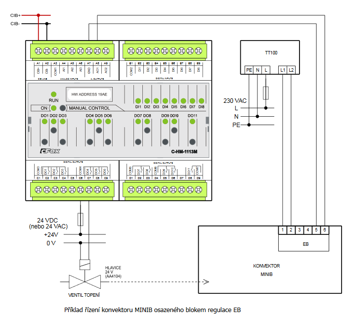
| Module connection |
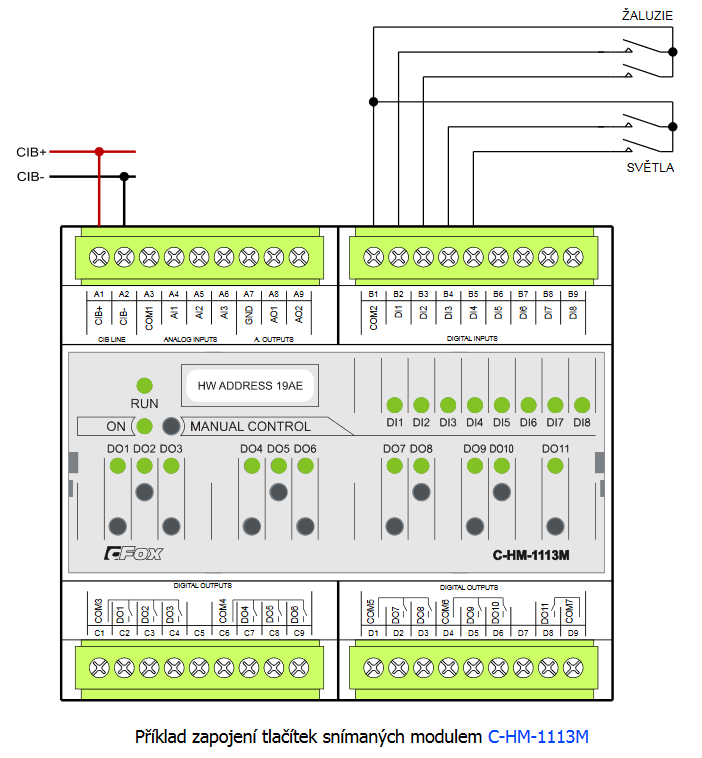
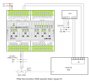
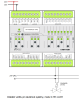
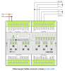
The combined module is implemented as a CIB bus module, which provides communication. The power supply of the module is from an external source. The CIB bus can have any topology and branching up to a distance of 500 m and up to 32 units on one CIB branch. The CIB bus master is basic a FOXTROT unit or module, for example MI2-02M. Further information can be found in the manual Peripheral modules on the CIB TXV 004 13. An example of module connection is shown in the following figure. |
| Module operation | |
| Module configuration | The module is operated, set up and diagnosed from the Mosaic development environment. |
| Commissioning | The module is ready for operation after connecting the supply voltage. The MODE button is available on the module panel to display the currently set Ethernet IP address. The parameters of all interfaces are set in the Mosaic development environment. |
| Module diagnostics | The basic diagnostic system of the module is a part of its standard software. It operates from module power on and operates independently of the user. Diagnostic error states of the module and connected peripheral modules of the assembly are signaled |
| Maintenance | |
| Description | The module does not require any maintenance under general installation conditions. |
| Notice | Because the module contains semiconductor components, it is necessary to follow the principles for working with electrostatic sensitive components when handling the removed cover. It is not allowed to directly touch the printed circuit boards without protective measures !!! |
| Warranty | |
| Generally | Warranty and complaint conditions are governed by the Terms and Conditions of Teco a.s. |
| Notice | You must meet all the conditions of this documentation before turning on the system. The system must not be put into service unless it has been verified and confirmed that the machinery meets the requirements of Directive 89/392 / EEC, in so far as it applies to it. Documentation subject to change. |
HW documentation
C-HM-1113M - Basic documentation
1.27 MB, (EN)
User manuals
Peripheral module on CIB-Common Installation Bus(R) (cs), TXV00413_01
14.01 MB
Peripheral modules on the CIB Common Installation Bus(R) (en), TXV00413_02
13.94 MB, (EN, RU, DE, UA)
Files for designers
Foxtrot 2 - library of elements in DXF and DWG formats, v. 2025/08.
21.80 MB
Foxtrot 2 - element library for SchemataCAD, v. 2025/08.
6.96 MB
EC - Declaration of Conformity
Foxtrot - EC Declaration of conformity
295.20 kB, (EN, RU, DE, UA)
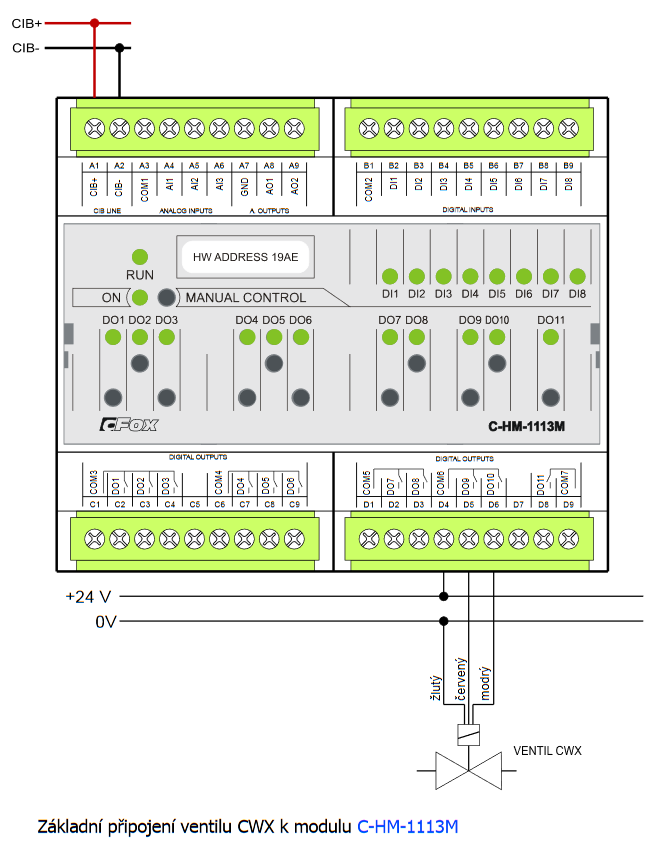
- C-HM-1113M - Fig. 1 The basic connection of the C-HM-1113M module Notes: The DI1 to DI8 inputs are intended only for connecting potential free contacts. The voltage on the COM2 common terminal opposite the GND terminal (analogically...
- Power dissipation of modules for calculation of switchboard heating - ...al inputs, 14xDI including double-balanced, 4M C-IB-1800M 2,0 W TXN 133 10 C-HM-1113M; CIB, 3x AI, 8x DI, 2x AO, 10x RO/5A, 1xRO/16A C-HM-1113M 3,5 W TXN 133 1...
- On-off drives (Alpha AA) controlled by a relay output - ...contact). Any relay output can be used for switching using an element in the control panel, e.g. the outputs in the C-HM-1113M etc. Fig. 1. An example of connection – a two-position drive (actuator) for ra...
- CIB power supply – principles, optimization - ...modules in one CIB is 32. This number must NEVER be exceeded. In the case of modules supplied from the CIB (e.g. the C-HM-1113M ) with a higher maximum power consumption, the total number of modules connected to the bus must be decreased, t...
- R-HM-1113M - The module is no longer for sale The R-HM-1113M module is functionally fully consistent with the C-HM-1113M module (the inputs, outputs). The only difference is in communication. The module is in a wireless version – a periphery mo...
- C-HM-1121M - ... The parameters of the analogue inputs and outputs (including their internal wiring) are consistent with the C-HM-1113M module (see the previous chapter)....
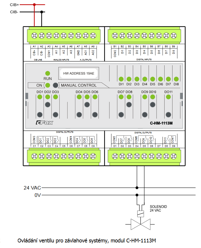
- Controlling valves (solenoid) for the irrigation systems, CFox - ....3 . are controlled in a similar way. Fig. 1. Controlling the valves for the irrigation systems, the C-HM-1113M module...
- Valves for controlling water (the main water valve, etc.) - ...Fig. 1. Mechanical dimensions of the CWX valves. Fig. 2. Basic wiring of the CWX valve to the C-HM-1113M module Notes: The valve control is terminated in the cable with coloured insula...
- The push-buttons scanned by the C-IB-1113M module in the control panel - ...ital inputs. Installations with assumed placement of the control system modules in the control panel can also use the C-HM-1113M and the C-HM-1121M modules. They should be placed in the main control panel (together with the basic modu...
- Switching a common source with independent control of several LED strips - ...ff the entire source (to avoid permanent power consumption when the lighting is switched off), it is recommended to use the C-HM-1113M (or C-HM-1121M ) modules: to switch the source, the 16 A output can be used (DO11, this output is designated for...
- Switching of LED lighting, light bulbs, fluorescent lamps, etc. - ...ith short-term switching current up to 80 A C-OR-0202B 2 relay outputs with short-term switching current up to 80 A C-HM-1113M 1 relay output with short-term switching current up to 800 A C-HM-1121M 3 relay outputs with short-term swit...
- Measurements of dewing (condensation of air humidity) - In order to prevent condensation on piping, cooling ceilings, walls of equipment, etc., there are special resistive dewing probes used ( Chap.11.4.1 ). By modifying the properties of a sensitive polymer layer they allow measuring high humidity....
- Measurement of radiant heat in halls (industrial heating) - The P30PA resistance sensors of radiant heat are designed to detect and measure the radiant component of heat in larger rooms and halls with a dry environment. The sensors capture the efficient radiant heat component in the monitored space. Good me...
- The separate temperature sensor S-TS-01R, connected to the AI of the system - The interior temperature can be measured with the S-TS-01R stand-alone temperature sensor (e.g. the NTC 12k) designed according to the customer's requirements. The sensor is available in ABB Time design under the order number TXN 134 01.01 (ba...
No data available.