


C-DM-0002L-10VTXN 133 78
C-DM-0002L-10V; CIB, 2x dimmer with 0-10V output for dimming ballasts LED or fluorescent lamps, 2x RO
| DI | |
|---|---|
| DI/AI | |
| DO | 2x RO |
| AI | |
| AO | 2x AO |
| COM | 1x CIB slave |
| SENSOR |
| Picture | Variant | Variant description |
|---|---|---|

|
C-DM-0002L-10V |
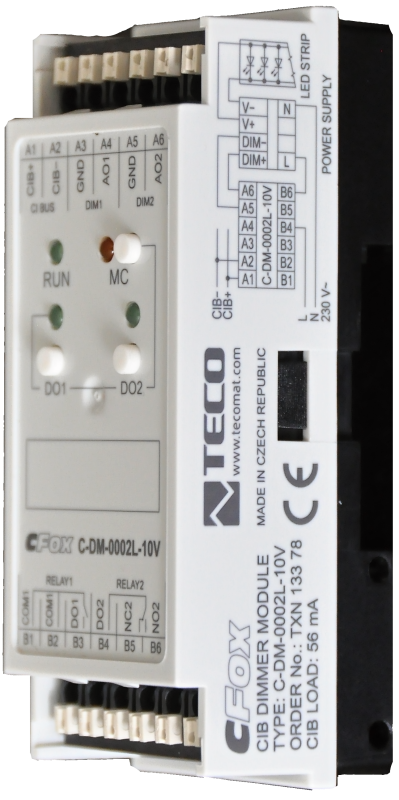
The C-DM-0002L-10V module is designed for independent two-channel control of electronic LED ballasts or fluorescent lamps, controlled by 0-10 V DC or 1-10 V DC.
To completely disconnect the ballasts from the main power supply, the module contains 2 relay outputs, one with an NC contact and the other with changeover contacts.
Of course, analog inputs and relay outputs can also be used universally for other purposes.
The module is designed for a DIN rail switchboard, but it can also be built into the body of the luminaire. It is connected to the Foxtrot basic module via a two-wire CIB Common Installation Bus®.
| Order num. | TXN 133 78 |
|---|---|
| Teco code | TXN 133 78 |
| Categories | CFox - Modules on DIN rail |
| Tags | - |
| COM - System buses | |
|---|---|
| CIB - Common Installation Bus (R): Installation I/O bus | 1x CIB slave |
| RO - Parameters of binary relay outputs (group A) | |
| Number of relay outputs | 1 |
| Output type | electromechanical relay, unprotected output |
| Contact type | NO - Normally Open |
| Switching voltage | max. 400 V AC |
| Switching power | 4000 VA max., 384 W max. |
| Short-term output overload - inrush | max. 800 A (max. 200 μs) |
| Contact closing time | typ. 10 ms |
| Contact opening time | typ. 5ms |
| Mechanical life | min. 5,000,000 cycles |
| Electrical life at rated load | min. 50,000 switchings |
| Short-circuit protection | No |
| Treatment of inductive load | External RC element, varistor (AC), diode (DC) |
| Insulation voltage between outputs and internal circuits | 4000 V AC |
| Insulation voltage between contacts | 1250 V AC |
| RO - Parameters of binary relay outputs (group B) | |
| Parameters valid for the terminals | DO2 |
| Number of relay outputs | 1 |
| Output type | electromechanical relay, unprotected output |
| Contact type | NO / NC changeover contact |
| Switching current | 16 A max., 100 mA min. |
| Switching voltage | 440 V AC/ 300 V DC |
| Switching power | 4000 VA |
| Short-circuit protection | No |
| Short-term output overload | 80 A max. (20 ms max.) |
| Contact closing time | typ. 10 ms |
| Contact opening time | typ. 5 ms |
| Mechanical life | min. 10,000,000 cycles |
| Electrical life at rated load | min. 10,000 switchings (inrush 80 A) |
| Treatment of inductive load | External RC element, varistor (AC), diode (DC) |
| Insulation voltage between outputs and internal circuits | 5000 V AC |
| Insulation voltage between contacts | 1000 V AC |
| AO - Analog output parameters | |
| Parameters valid for the terminals | AO1 |
| Galvanic isolation from internal circuits | No |
| Output type | active voltage output |
| Voltage output - voltage | 0 - 10 V |
| Voltage output - Minimum resolution | 1 % |
| Voltage output - Adjustable range | 0 ÷ 125 % Ujm |
| Voltage output - Load resistance | >1 kΩ |
| Voltage output - Load capacity | 50 nF |
| Power supply | |
| Supply voltage, tolerances | 24/27 V DC from CIB bus |
| Power supply from CIB - maximum current consumption (mA) | 60 mA |
| Galvanic separation of power supply from internal circuits | No |
| Power supply from CIB - internal protection | Yes, returnable fuse |
| Size and weight | |
| Weight approx. | 200 g |
| Product dimensions (width x height x depth) | 35 × 92 × 32 mm |
| Operating conditions, product standards | |
| Product standard | ČSN EN 60730-1 ed. 3:2012 (mod IEC 60730-1:2010) |
| Protection class of electrical object | II, according to ČSN EN 61140 ed.3: 2016 (idt IEC 61140:2016) |
| IP rating (Ingress Protection) according to ČSN EN 60529: 1993 (idt IEC 529: 1989) | IP20 |
| Operating areas | Normal, acc. ČSN 33 2000-1 ed.2: 2009 (mod IEC 60354-1:2005) |
| Degree of pollution | 1, according to ČSN EN 60664-1 ed.2:2008 ( idt IEC 60664-1:2007) |
| Overvoltage category installation | II, according to EN 60664-1 ed_2: 2008 (idt IEC 60641-1: 2007) |
| Type of device | Module on DIN rail |
| Working position | Vertical |
| Type of operation (operating frequency) | Continuous |
| Ambient operating temperatures | -10 °C to + 55 °C |
| Operating relative humidity | from 10 % up to 95 % without condensation |
| Operating atmospheric pressure | min. 70 kPa (<3,000 m above sea level) |
| Storage temperatures | –25 °C to +70 °C |
| Electromagnetic compatibility, Mechanical endurance | |
| Electromagnetic compatibility / Emission | A, according to EN 55032 ed. 2: 2017 (idt CISPR 32: 2015) |
| Emmisions - note | In premises where the use of radio and television receivers can be expected to be used a distance of 10 m from these devices may cause radio interference. In such a case, the user may be required to take appropriate action. |
| Electromagnetic compatibility / Immunity | min. according to ČSN EN 60730-1 ed.3: 2012 |
| Sinusoidal vibration endurance | 10 Hz to 57 Hz, amplitude 0,075 mm, 57 Hz to 150 Hz, acceleration 1 G (Fc test according to EN 60068-2-6: 1997 (idt IEC 68-2-6: 1995), 10 cycles per axis.) |
| Packaginng, transportation, storage | |
| Description | The module is packed in a paper box. This documentation is also part of the package. The outer packaging is carried out according to the scope of the order and the method of transport in a transport package provided with labels and other data necessary for transport. The product must not be exposed to direct weather conditions during transport and storage. Malting of the product is only allowed in clean rooms without conductive dust, aggressive gases and vapors. The most suitable storage temperature is 20 ° C |
| Installation | |
| Assembly description | The module is mounted in a vertical position on the U-rail ČSN EN 50022. Installation of the assembly (basic module and possibly peripheral modules) is performed according to TXV 004 13. |
| Connection | |
| Connection of power and system communication | terminal block with spring terminal 1.5 mm2, push-in |
| Connection of inputs / outputs | terminal block with spring terminal 1.5 mm2, push-in |
| Module installation tools | (-) 2 mm, flat screwdriver |
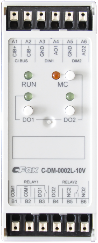
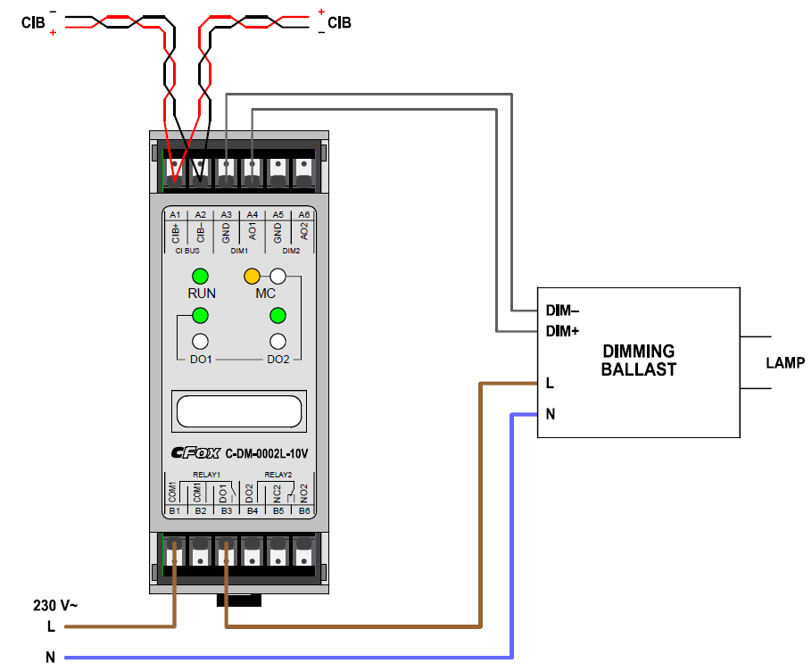
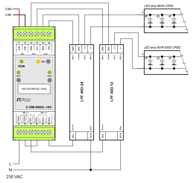
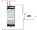
| Module connection | The connection of the module to the CIB bus, analog outputs and contacts of relay outputs is realized by two terminal blocks with spring terminals. This is done by inserting the wire directly into the wire hole on the terminal. These terminals are intended for the connection of a solid conductor. If it is necessary to connect the cable conductor, it is necessary to crimp suitable cable sleeves at its ends. The suitable stripping length of the conductor / sleeve is 8 mm. The wire is released from the clamp by pushing the tip of a flat-blade screwdriver (recommended size 0.4x2 mm) inserted into a groove in a bright target located near the hole for the wire. The CIB bus (terminals A1, A2) is connected to the upper terminal block. The number of modules on the CIB bus is limited by the maximum permitted bus current. Furthermore, the analog outputs AO1 and AO2 (terminals A3 to A6) are output here. The contacts of relay outputs DO1 and DO2 (terminals B1 to B6) are connected to the lower terminal board. An example of the module connection is shown in the following figure (terminal designations on the ballast used may differ depending on the specific type used). |
| Module operation | |
| Commissioning | The module is operated, set and diagnosed from the MOSAIC programming environment or other parameterization software. The module is ready for operation after connecting the supply voltage and the CIB bus. The HW address is indicated on the label on the module. |
| Module diagnostics | The basic diagnostic system of the module is part of its standard software. It has been in operation since the module power was turned on and works independently of the user. Diagnosed error states of the module and connected peripheral modules of the assembly are signaled in the status word of the module and on the module panel |
| Maintenance | |
| Description | The module does not require any maintenance under general installation conditions. The operations in which a part of the module has to be dismantled must always be carried out with the supply voltage disconnected. |
| Notice | Because the module contains semiconductor components, it is necessary to follow the principles for working with electrostatic sensitive components when handling the removed cover. It is not allowed to directly touch the printed circuit boards without protective measures !!! |
| Warranty | |
| Generally | Warranty and complaint conditions are governed by the Terms and Conditions of Teco a.s. |
| Notice | You must meet all the conditions of this documentation before turning on the system. The system must not be put into service unless it has been verified and confirmed that the machinery meets the requirements of Directive 89/392 / EEC, in so far as it applies to it. Documentation subject to change. |
HW documentation
C-DM-0002L-10V - Basic documentation
753.70 kB, (EN)
User manuals
Peripheral module on CIB-Common Installation Bus(R) (cs), TXV00413_01
14.01 MB
Peripheral modules on the CIB Common Installation Bus(R) (en), TXV00413_02
13.94 MB, (EN, RU, DE, UA)
Scheme
C-DM-0002L-10V
42.64 kB
C-DM-0002L-10V
44.49 kB
C-DM-0002L-10V
47.12 kB
Files for designers
Foxtrot 2 - library of elements in DXF and DWG formats, v. 2025/08.
21.80 MB
Foxtrot 2 - element library for SchemataCAD, v. 2025/08.
6.96 MB
EC - Declaration of Conformity
Foxtrot - EC Declaration of conformity
295.20 kB, (EN, RU, DE, UA)
- Power dissipation of modules for calculation of switchboard heating - ...uator, 6x 2RO - dependent switching, 230VAC/5A C-JC-0006M 1,8 W TXN 133 78 C-DM-0002L-10V; CIB, C-DM-0002L-10V 1,4 W TXN 133 80 C-BM-0202M Module (cur...
- Dimming LED strips by controlled 230 V power supply, e.g. LPF produced by Mean Well - ...olled by analogue signal 0 ÷ 10 V, and either any analogue Foxtrot system output can be used, or a specialized module C-DM-0002L-10V, which is equipped with programmable control in time (ramp), similarly to other C-DM series modules. F...
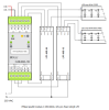
- Smart City - modules for controlled control of ballasts for public lighting - ...nbsp; Fig. Moduly pro stmívání jednoho až dvou předřadníků pro použití v lampách veřejného osvětlení. C-DM-0002L-10V is two-channel on CIB buses, The R-SL-0201L-A is single-channel connected to the Foxtrot control panel wir...
No data available.