

C-DM-0006M-ULEDTXN 133 45
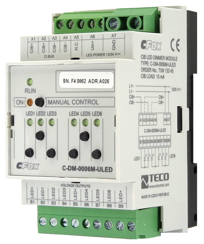
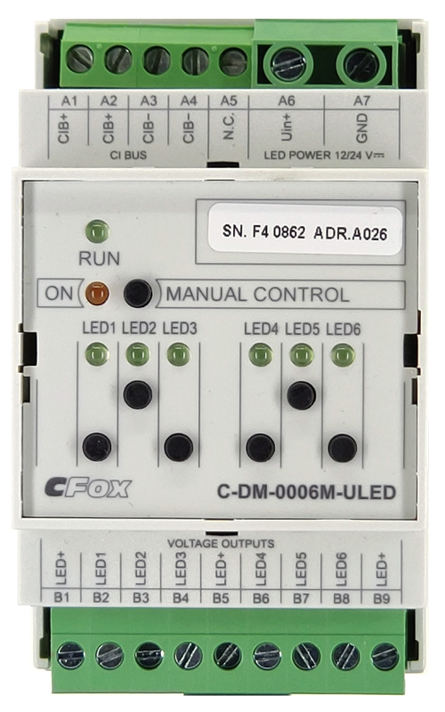
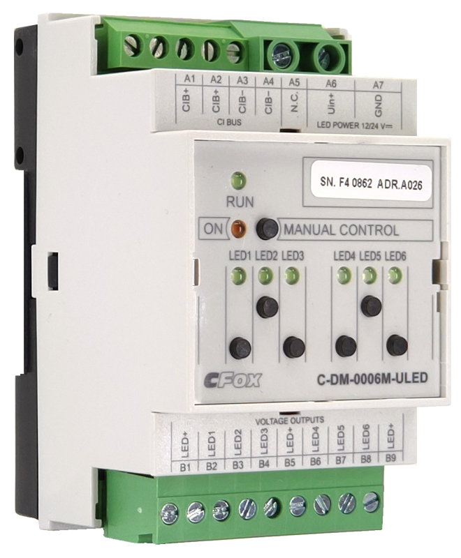
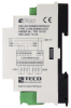
C-DM-0006M ULED; CIB, 6 channel dimming module for LED strips 12-24VDC, max. 4A/channel
| DI | |
|---|---|
| DI/AI | |
| DO | |
| AI | |
| AO | 6x LED strip dimmer |
| COM | 1x CIB slave |
| SENSOR |
| Picture | Variant | Variant description |
|---|---|---|

|
C-DM-0006M-ULED |
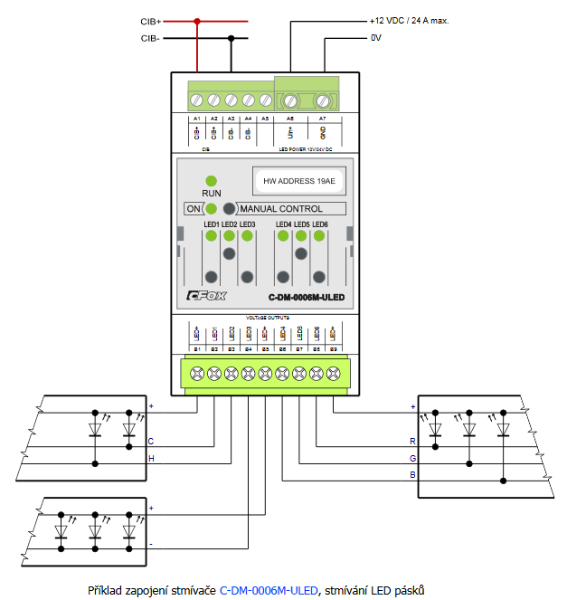
The C-DM-0006M-ULED module is a 6-channel dimming actuator 0-100% for LED strips in the supply voltage range of 12-48 V DC, with a load capacity of max. 4 A / channel. each channel can be controlled separately. It can also be used as a two-channel RGB actuator, or for two-channel control of the chromaticity of white lighting.
The module is designed for a DIN rail switchboard and is connected to the basic module via a two-wire CIB Common Installation Bus®.
The module is designed for a DIN rail switchboard and is connected to the basic module via a two-wire CIB Common Installation Bus®.
| Order num. | TXN 133 45 |
|---|---|
| Teco code | TXN 133 45 |
| Categories | CFox - Modules on DIN rail |
| Tags | - |
| COM - System buses | |
|---|---|
| CIB - Common Installation Bus (R): Installation I/O bus | 1x CIB slave |
| AO - Analog output parameters | |
| Number of analog outputs | 6 |
| The number of groups of analogue outputs | 2 |
| Number of outputs in group | 3 |
| Number of outputs and their organization into groups |
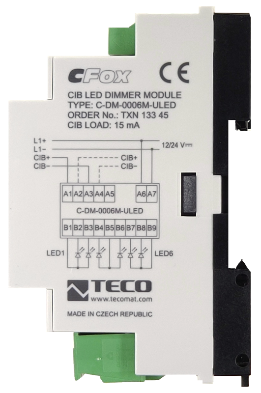
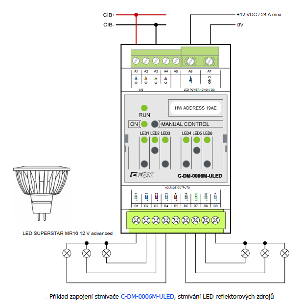
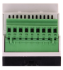
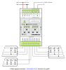
Each of terminals B1, B5, B9 (LED+) has a maximum current of 10A, but the sum of currents through these terminals must not exceed 24A. A maximum of 4A current may flow through each of terminals B2, B3, B4, B6, B7, B8, (LED1 - 6)but the total sum of these currents through terminals B2, B3, B4, B6, B7, B8 must not exceed 24A. The operating voltage is 12 - 48V DC, while the value of 48V DC applies from serial number 1226 (April 2017), up to this serial number is the maximum value of 24V DC. |
| Common wire of group | plus |
| Galvanic isolation from internal circuits | No |
| Output type | active voltage output in switching mode |
| External power supply | max 48V DC (up to serial number 1226 only 24V DC) |
| Power supply | |
| Supply voltage, tolerances | 24/27 V DC from CIB bus |
| Auxiliary power supply - voltage |
The supply voltage for the LEDs must be selected with regard to the LED light sources used. The outputs for LED strips have a common positive supply pole (anode) marked as LED +. For LED + outputs it is necessary to observe the maximum current of one terminal 10 A, The supply voltage is usually from 12 V DC and up to a maximum of 48 V DC. The 48V DC power supply is valid from serial number 1226 (April 2017), up to this serial no. only 24V DC! |
| Typical power input | 3 W |
| Maximum power input | 5 W |
| Module thermal/power loss | 5 W |
| Maximum current consumption (mA) | < 20 mA |
| Galvanic separation of power supply from internal circuits | No |
| Internal protection | Yes, PTC reversible fuse |
| Size and weight | |
| Weight approx. | 100 g |
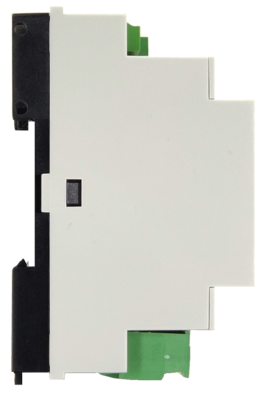
| Product dimensions (width x height x depth) | 52 x 90 x 58 mm |
| Module width in multiples of M (17.5 mm) | 3M |
| Module width | 52 mm |
| Module height | 90 mm |
| Module depth | 58 mm |
| Operating conditions, product standards | |
| Product standard | ČSN EN 60730-1 ed.4 :2017 (EN 60730-1:2016) -Automatic electronic control device (for household and similar purposes) |
| Protection class of electrical object | III, according to ČSN EN 61140 ed.3: 2016 (idt IEC 61140:2016) |
| IP rating (Ingress Protection) according to ČSN EN 60529: 1993 (idt IEC 529: 1989) | IP20 |
| Operating areas | Normal, according to ČSN 33 2000-3: 1995 (mod IEC 364-3: 1993) |
| Degree of pollution | 1, according to ČSN EN 60664-1 ed.2:2008 ( idt IEC 60664-1:2007) |
| Overvoltage category installation | III, according to EN 60664-1 ed_2: 2008 (idt IEC 60641-1: 2007) |
| Type of device | Module on DIN rail |
| Working position | Vertical |
| Type of operation (operating frequency) | Continuous |
| Ambient operating temperatures | 0 °C to +40 °C |
| Operating temperature minimum (° C) | 0°C |
| Operating relative humidity | from 10 % up to 95 % without condensation |
| Operating atmospheric pressure | min. 70 kPa (<3,000 m above sea level) |
| Storage temperatures | –25 °C to +70 °C |
| Electromagnetic compatibility, Mechanical endurance | |
| Electromagnetic compatibility / Emission | A, according to EN 55032 ed. 2: 2017 (idt CISPR 32: 2015) |
| Emmisions - note | In premises where the use of radio and television receivers can be expected to be used a distance of 10 m from these devices may cause radio interference. In such a case, the user may be required to take appropriate action. |
| Electromagnetic compatibility / Immunity | min. as required by EN 61131-2: 2007 |
| Sinusoidal vibration endurance | 10 Hz to 57 Hz, amplitude 0,075 mm, 57 Hz to 150 Hz, acceleration 1 G (Fc test according to EN 60068-2-6: 1997 (idt IEC 68-2-6: 1995), 10 cycles per axis.) |
| Packaginng, transportation, storage | |
| Description | The module is packed in a paper box. This documentation is also part of the package. The outer packaging is carried out according to the scope of the order and the method of transport in a transport package provided with labels and other data necessary for transport. The product must not be exposed to direct weather conditions during transport and storage. Malting of the product is only allowed in clean rooms without conductive dust, aggressive gases and vapors. The most suitable storage temperature is 20 ° C |
| Installation | |
| Assembly description | Switchboard mounting |
| Attention! | The device may contain parts with dangerous voltages, covers being removed, or cabling manipulated, or disconnect the appropriate circuits or turn off the power !. |
| Connection | |
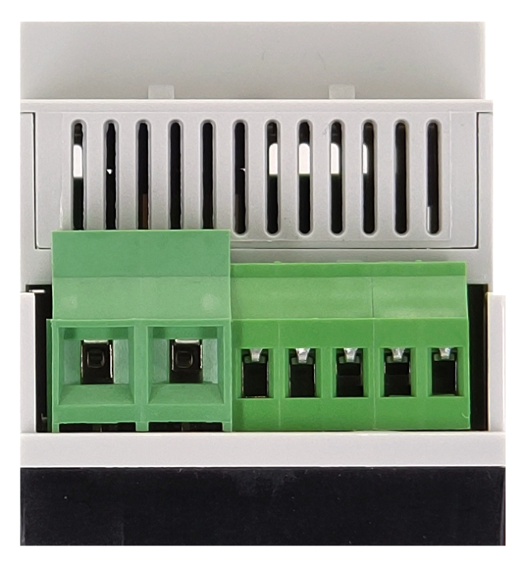
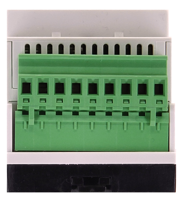
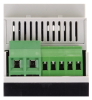
| Connection of power and system communication | connector with 2.5 mm2 screw terminal |
| Connection of inputs / outputs | connector with screw terminal 2.5 mm2 |
| Module installation tools | (-) 3 mm, flat screwdriver |
| Module operation | |
| Module configuration | The module is operated, set up and diagnosed from the Mosaic development environment. |
| Module diagnostics | The basic diagnostic system of the module is a part of its standard software. It operates from module power on and operates independently of the user. Diagnostic error states of the module and connected peripheral modules of the assembly are signaled |
| Maintenance | |
| Description | The module does not require any maintenance under general installation conditions. The operations in which a part of the module has to be dismantled must always be carried out with the supply voltage disconnected. |
| Notice | Because the module contains semiconductor components, it is necessary to follow the principles for working with electrostatic sensitive components when handling the removed cover. It is not allowed to directly touch the printed circuit boards without protective measures !!! |
| Warranty | |
| Generally | Warranty and complaint conditions are governed by the Terms and Conditions of Teco a.s. |
| Notice | You must meet all the conditions of this documentation before turning on the system. The system must not be put into service unless it has been verified and confirmed that the machinery meets the requirements of Directive 89/392 / EEC, in so far as it applies to it. Documentation subject to change. |
HW documentation
C-DM-0006M-ULED - Basic documentation
1.02 MB, (EN)
User manuals
Peripheral module on CIB-Common Installation Bus(R) (cs), TXV00413_01
14.01 MB
Peripheral modules on the CIB Common Installation Bus(R) (en), TXV00413_02
13.94 MB, (EN, RU, DE, UA)
EC - Declaration of Conformity
Foxtrot - EC Declaration of conformity
295.20 kB, (EN, RU, DE, UA)
Files for designers
Foxtrot 2 - library of elements in DXF and DWG formats, v. 2025/08.
21.80 MB
Foxtrot 2 - element library for SchemataCAD, v. 2025/08.
6.96 MB
- C-DM-0006M-ULED - ...ieve higher efficiency than the strips powered by nominal voltage). These strips must not be connected to the outputs of the C-DM-0006M-ULED module, as the LEDs could be destroyed! These LED strips powered by nominal current must be dimmed by the C-D...
- An example of wiring a power LED strip over a longer distance to C-DM-0006M-ULED - The C-DM-0006M-ULED module is designed for a DIN rail mounting. Likewise, the power supply for the LEDs (e.g. DR-60-12) is designed to be installed in the distribution cabinet, which means that in most cases the controlled voltage must be lea...
- Power dissipation of modules for calculation of switchboard heating - ...C-HM-0308M; CIB, 3x AI/DI, 2x AO, 6x RO/5A C-HM-0308M 2,1 W TXN 133 45 C-DM-0006M-ULED; CIB, 6 channel dimming module for LED strips 12-24VDC, max. 4A/channel C-DM-0006M-ULED 5,0...
- Dimming LED point reflector sources (MR16) - The dimmer C-DM-0006M-ULED can also dim low voltage dimmable reflector sources, e.g. LED SUPERSTAR MR16 12 V advanced. These LED sources are connected in the same way as LED strips and similar sources. However, some sources cannot be connect...
- Dimming RGB, monochrome and two-colour LED strips - For continuous brightness control of LED strips with 12 V or 24 VDC nominal voltage there is the C-DM-0006M-ULED module.Maximum current in one output is 4 A, maximum current in the common powering terminal (terminals A6, A7) is 24 A....
- LED dimming, 12 V, 24 V voltage control - ...). Slightly less common are LED strips with 24 VDC nominal voltage. For these LED strips there is a dimming module C-DM-0006M-ULED . The module can dim and power LED strips with 12 ÷ 24 VDC nominal voltage, 6 independent channels i...
- DR-60-24 power supply - The DR-60-24 power supply is a mains switch-mode power supply with 24 V continuous output voltage and 2.5 A. It is designed to supply power to the Foxtrot control systems without a backup. Basic properties are identical with the DR-60-12 power supp...
No data available.