
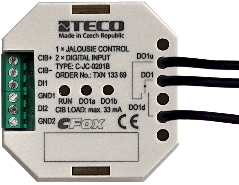


C-JC-0201BTXN 133 69
C-JC-0201B; CIB, 1x jalousie actor (2xRO with dependent switching, local function). 230VAC/16A, 2x DI
| DI | 2x DI |
|---|---|
| DI/AI | |
| DO | 1 shutter / motor output |
| AI | |
| AO | |
| COM | 1x CIB slave |
| SENSOR |
| Picture | Variant | Variant description |
|---|---|---|

|
C-JC-0201B |
C-JC-0201B is a module on the CIB bus that contains
- 2 relay outputs interlocked, each separately connected to the terminal board
- 2 binary inputs for connection of potential-free contacts, which evaluate short and long presses.
When the CIB master is not connected or not communicating, the outputs can be controlled manually if the control contacts are connected directly to the module inputs.
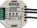
The module is mechanically designed in the "box" type for mounting in the installation box.
- 2 relay outputs interlocked, each separately connected to the terminal board
- 2 binary inputs for connection of potential-free contacts, which evaluate short and long presses.
When the CIB master is not connected or not communicating, the outputs can be controlled manually if the control contacts are connected directly to the module inputs.
The module is mechanically designed in the "box" type for mounting in the installation box.
| Order num. | TXN 133 69 |
|---|---|
| Teco code | TXN 133 69 |
| Categories | CFox - Built-in modules |
| Tags | - |
| COM - System buses | |
|---|---|
| CIB - Common Installation Bus (R): Installation I/O bus | 1x CIB slave |
| DI - Parameters of binary inputs DC (group A) | |
| Number of inputs in group | 1 |
| Input type | active (for dry contacts connection) |
| Galvanic separation of inputs from CIB bus | No |
| Max. measuring voltage on the connected contact | 3,3 V DC |
| Internal input resistance | 2 kΩ |
| Max. resistance for closed contact, log. 1 | < 0,5 kΩ |
| Min. resistance for open contact, log. 0 | > 1,5 kΩ |
| RO - Parameters of binary relay outputs (group A) | |
| Parameters valid for the terminals | DO1u, DO1d |
| Number of relay outputs | 2 |
| Number of output groups | 1 |
| Number of outputs in group | 2 |
| Output type | electromechanical relay, unprotected output |
| Contact type | Up-0-Down, three-state actuator |
| Galvanic separation from internal circuits | Yes |
| Diagnose | Alarm signaling on panel module |
| Switching current | 16 A max., 100 mA min. |
| Switching voltage | 300 V max., 5 V min. |
| Switching power | 4000 VA max., 384 W max. |
| Contact closing time | typ. 15 ms |
| Contact opening time | typ. 5ms |
| Reverse delay | 300 ms |
| Mechanical life | min. 20 000 000 cycles |
| Electrical life at rated load | min. 50,000 switchings |
| Short-circuit protection | No |
| Treatment of inductive load | External RC element, varistor (AC), diode (DC) |
| Insulation voltage between outputs and internal circuits | 4000 V AC |
| Insulation voltage between contacts | 1000 V AC |
| Power supply | |
| Supply voltage, tolerances | 24/27 V DC from CIB bus |
| Power supply from CIB - maximum current consumption (mA) | 33 mA |
| Galvanic separation of power supply from internal circuits | No |
| Internal protection | Yes, PTC reversible fuse |
| Operating conditions, product standards | |
| Product standard | ČSN EN 60730-1 ed. 2:2001 (mod IEC 60730-1:1999) |
| Protection class of electrical object | III, according to ČSN EN 61140 ed.3: 2016 (idt IEC 61140:2016) |
| IP rating (Ingress Protection) according to ČSN EN 60529: 1993 (idt IEC 529: 1989) | IP20 |
| Operating areas | Normal, acc. ČSN 33 2000-1 ed.2: 2009 (mod IEC 60354-1:2005) |
| Degree of pollution | 1, according to ČSN EN 60664-1 ed.2:2008 ( idt IEC 60664-1:2007) |
| Overvoltage category installation | II, acc. ČSN EN 60664-1:2004 (mod IEC 606641:1992) |
| Type of device | In the installation box, under the cover |
| Working position | Any |
| Type of operation (operating frequency) | Continuous |
| Ambient operating temperatures | -20 °C to + 55 °C |
| Operating temperature maximum (° C) | +55°C |
| Operating temperature minimum (° C) | -20°C |
| Operating relative humidity | from 10 % up to 95 % without condensation |
| Operating atmospheric pressure | min. 70 kPa (<3,000 m above sea level) |
| Storage temperatures | –25 °C to +70 °C |
| Electromagnetic compatibility, Mechanical endurance | |
| Electromagnetic compatibility / Emission | B, according to EN 55022: 1999 (mod CISPR22: 1997) |
| Electromagnetic compatibility / Immunity | min. according to ČSN EN 60730-1 ed.2: 2001 |
| Sinusoidal vibration endurance | 10 Hz to 57 Hz, amplitude 0,075 mm, 57 Hz to 150 Hz, acceleration 1 G (Fc test according to EN 60068-2-6: 1997 (idt IEC 68-2-6: 1995), 10 cycles per axis.) |
| Installation | |
| Assembly description |
Relay module C-JC-0201B can be mounted in any position in installation box under the lid or under the device in the installation box boxes. The installation is performed according to TXV 004 13. |
| Attention! | The device may contain parts with dangerous voltages, covers being removed, or cabling manipulated, or disconnect the appropriate circuits or turn off the power !. |
| Connection | |
| Connection description |
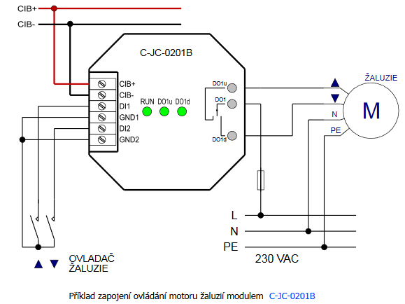
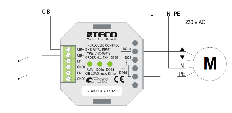
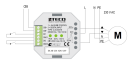
The C-JC-0201B module has a CIB bus and 2 inputs are connected to screw terminals, the relay contacts for the control of blinds are connected by means of insulated conductors with a length of approx. 80 mm terminated in sockets. The number of modules on the line is limited by the maximum allowed line current. Further information can be found in the manual Peripheral modules on the CIB TXV 004 13. An example of module connection is shown in the following figure. |
| Connection of power and system communication | terminal block with screw terminal 1.5 mm2 |
| Specific I / O | Blind / motor output - Up and Down contacts |
| Connection of specific I / O | Insulated wires with sleeve |
| Module installation tools | (-) 3 mm, flat screwdriver |
| Module operation | |
| Commissioning | The module is operated, set and diagnosed from the MOSAIC programming environment or other parameterization software. The module is ready for operation after connecting the supply voltage and the CIB bus. The HW address is indicated on the label on the module. |
| Module diagnostics | The basic diagnostics is performed internally and the result is available in the relevant registers of the Mosaic environment. When the power is turned on, the RUN LED lights up green, after communication is established, it starts flashing. The switching status of the relay is indicated by a green LED. |
| Maintenance | |
| Description | The module does not require any maintenance under general installation conditions. The operations in which a part of the module has to be dismantled must always be carried out with the supply voltage disconnected. |
| Notice | Because the module contains semiconductor components, it is necessary to follow the principles for working with electrostatic sensitive components when handling the removed cover. It is not allowed to directly touch the printed circuit boards without protective measures !!! |
| Warranty | |
| Generally | Warranty and complaint conditions are governed by the Terms and Conditions of Teco a.s. |
| Notice | You must meet all the conditions of this documentation before turning on the system. The system must not be put into service unless it has been verified and confirmed that the machinery meets the requirements of Directive 89/392 / EEC, in so far as it applies to it. Documentation subject to change. |
HW documentation
C-JC-0201B - Basic documentation
1.10 MB, (EN)
User manuals
Peripheral module on CIB-Common Installation Bus(R) (cs), TXV00413_01
14.01 MB
Peripheral modules on the CIB Common Installation Bus(R) (en), TXV00413_02
13.94 MB, (EN, RU, DE, UA)
Files for designers
Foxtrot 2 - library of elements in DXF and DWG formats, v. 2025/08.
21.80 MB
Foxtrot 2 - element library for SchemataCAD, v. 2025/08.
6.96 MB
EC - Declaration of Conformity
Foxtrot - EC Declaration of conformity
295.20 kB, (EN, RU, DE, UA)
- C-JC-0201B, a module for blinds control - The C-JC-0201B module is equipped with one output intended for standard blinds control - i.e. the so-called three-point-control: opening-idle-closing. The module can also be used for three-point valve control, etc. The module is internally eq...
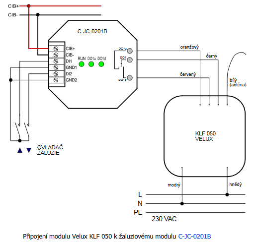
- Control of Velux roof windows - ...nsions are 49 x 47 x 28 mm and it is powered by 230 VAC. Fig. 1. Connecting the Velux KLF 050 module to the C-JC-0201B blinds module Notes: In this connection, the “up” position (switched DO1...
- Control of asynchronous motors for blinds and awnings, the C-JC-0202B - ...with reversing by switching the windings (similar to 3-point actuators for valves and dampers) we have a specialized module C-JC-0201B designed to control one louver and place it in the installation box near the shading element or directly in the l...
No data available.