


IT-1604TXN 116 04
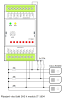
IT-1604, 8xAI: 16bit, 4-20mA, 0-10V, Ni1000, 2xAO: 10 bit/0÷10 V, GO
| DI | |
|---|---|
| DI/AI | |
| DO | |
| AI | 8x AI |
| AO | 2x A0 1x Vref |
| COM | |
| SENSOR |
| Picture | Variant | Variant description |
|---|---|---|

|
IT-1604 |
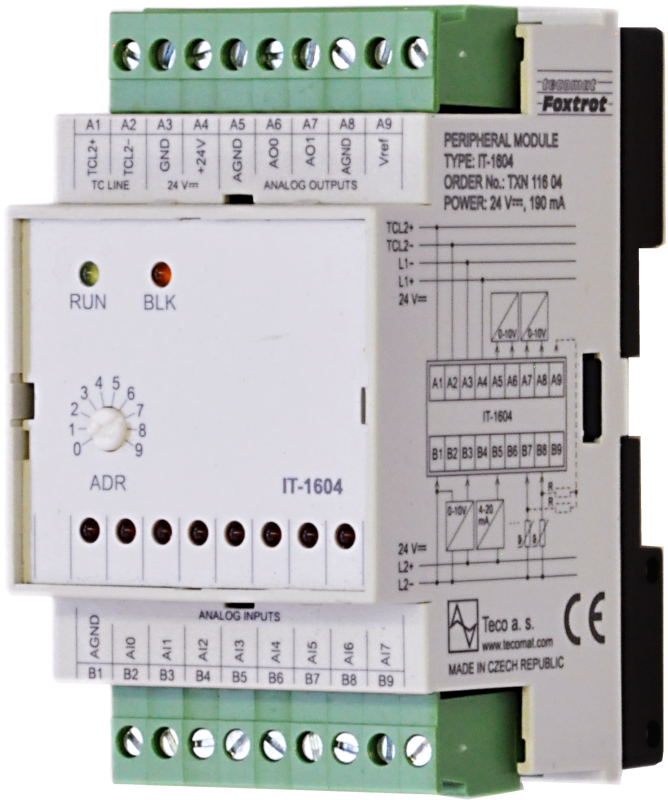
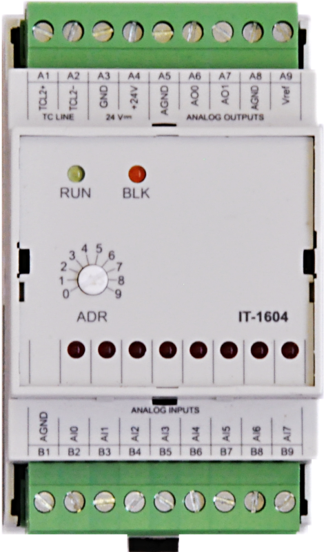
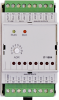
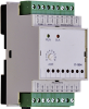
IT-1604 - expansion module contains 8 analog inputs with common terminal and 2 analog outputs with common terminal. The inputs are universal, independently configurable as voltage, current and for two-wire connection of passive resistance sensors. The resolution is 16 bits.
The module provides processing of the measured value, conversion to engineering units, etc. The analog outputs are voltage 0 ÷ 10 V with a resolution of 8 bits. The analog inputs and outputs are galvanically isolated from the input voltage, TCL2 communication and internal circuits. The status of each input is indicated on the module panel. The module is equipped with removable screw connectors. For current ranges, it is possible to give an external measuring resistor of 100 Ω to close the current loop even without a running machine. For a three-wire connection of passive sensors, it is necessary to use an external 7.5 kΩ resistor and supply the connection from the reference voltage Vref. The use of external resistors must be set in the MOSAIC environment.
The module provides processing of the measured value, conversion to engineering units, etc. The analog outputs are voltage 0 ÷ 10 V with a resolution of 8 bits. The analog inputs and outputs are galvanically isolated from the input voltage, TCL2 communication and internal circuits. The status of each input is indicated on the module panel. The module is equipped with removable screw connectors. For current ranges, it is possible to give an external measuring resistor of 100 Ω to close the current loop even without a running machine. For a three-wire connection of passive sensors, it is necessary to use an external 7.5 kΩ resistor and supply the connection from the reference voltage Vref. The use of external resistors must be set in the MOSAIC environment.
| Order num. | TXN 116 04 |
|---|---|
| Teco code | TXN 116 04 |
| Categories | Foxtrot - I / O Expansion Modules (TCL2) |
| Tags | - |
| COM - System buses | |
|---|---|
| TCL2 - system I/O bus | 1x TCL2 slave |
| AI - Organization of analog inputs | |
| Total number of analog inputs | 8 |
| Number of analog input groups | 1 |
| Organization of analog inputs into groups | 8x (AI0-AI7) |
| Input type | With common clamp |
| Common wire | Minus |
| Galvanic separation from internal circuits | Yes, 8 inputs together |
| Diagnostics | yes, signaling on the module panel and in status |
| Type of protection | integrated overvoltage protections |
| External power supply | No |
| Digital resolution | 16 bit |
| Lowest Bit Value (LSB) | see manual TXV 004 12.01 |
| Converter type | sigma-delta |
| Repeat time of sample | 500 ms typ. |
| Total System Input Move Time (TAID + TAIT) | 65 ms typ. |
| Operating modes | periodic input sensing |
| Filtration | low pass filter, digital comb filter 50/60 Hz |
| Insulation potential | 500 V DC between input and internal circuits |
| AI - Analog Input Ranges (Group A) | |
| Voltage | 0 to 10 V / 2,579 mV |
| Voltage | 0 to 5 V / 2,726 mV |
| Voltage | 0 to 2 V / 805.9 μV |
| Voltage | 0 -1 V |
| Voltage | 0 to 0.5 V |
| Input impedance in the voltage signal range | > 100 kΩ |
| Voltage input error - max. error at 25 ° C | ± 0.3% of full scale |
| Voltage input error - temperature coefficient | ± 0.02% of full scale / K |
| Voltage input error - non-linearity | ± 0.08% of full scale |
| Voltage input error - repeatability under steady state conditions | 0.05% of full scale |
| Permissible continuous overload - voltage input | ± 30 V each terminal AI against AGND |
| Current | 0 to 5 mA |
| Ccurrent | 0 to 20 mA / 8,059 μA |
| Current | 4-20 mA |
| Input impedance in the current signal range | 100 Ω |
| Current input error - maximum error at 25 ° C | ±0.4% of full scale |
| Error current input - temperature coefficient | ± 0.03% of full scale / K |
| Error current input - nonlinearity | ± 0.07% of full scale |
| Error current input - repeatability at steady-state conditions | 0.05% of full scale |
| Open input detection | Yes, in status word (under-range - only 4 - 20 mA range) |
| Passive sensor | Pt100, W100=1,385 (-90 to +400 °C) |
| Passive sensor | Pt100, W100 = 1,391 (-90 to +400 °C) |
| Passive sensor | Pt1000, W100 = 1,385 (-90 to +400 °C) |
| Passive sensor | Pt1000, W100 = 1,391 (-90 to +400 °C) |
| Passive sensor | Ni1000, W100 = 1,500 (–60 to +200 ° C) |
| Passive sensor | Ni1000, W100 = 1.617 (-60 to +200 ° C) |
| Passive sensor | Resistance transmitter 0-1 kOhm |
| Passive sensor | Resistance transmitter 0-2 kOhm |
| Passive sensor | Resistance transmitter 0-200 kOhm |
| Passive sensor | KTY81-121; PTC thermistor (-55 to + 125 °C) |
| Passive sensor | NTC Thermistor 12k / 25 °C (-40 to + 125 °C) |
| Input impedance in signal range RTD | > 7,5 kΩ |
| Resistance measurement error - maximum error at 25 ° C | ± 0.5% of full scale |
| Resistance measurement error - temperature coefficient | ± 0.05% of full scale / K |
| Resistance measurement error - non-linearity | ± 0.09% of full scale |
| Resistance measurement error - repeatability at steady conditions | 0.07% of full scale |
| Max. permissible permanent overload of analog input (without damage) | ± 30 V; each terminal AI against AGND |
| Detection of disconnected sensor | yes, in status word, range overflow |
| AO - Analog output parameters | |
| Common wire of group | minus |
| Galvanic isolation from internal circuits | Yes, along with the entrances |
| Output type | active voltage output |
| Type of protection | integrated overvoltage protections |
| Diagnostics | None |
| Max. permissible permanent overload (without damage) | ± 20 V, each terminal against AGND |
| Converter resolution | 10 bit |
| conversion time | 10 μs |
| Total Time to Move System Output (TAID + TAIT) | typ. 2 ms |
| Analog output error - maximum error at 25 ° C | ± 2% of full scale |
| Output repeat setting time | typ. 5 ms |
| Analog output error - temperature coefficient | ± 0.3% of full scale / K |
| Analog output error - linearity | ± 0.7% of full scale |
| Analog output error - repeatability under steady state conditions | ± 0.5% of full scale |
| Operating modes | periodic output settings |
| Voltage output - voltage | 0 - 10 V |
| Voltage output - Resolution 1 LSB | 10,546 mV |
| Voltage output - maximum output current | 10 mA |
| Calibration or verification to maintain nominal accuracy | 2 years |
| Insulation potentials under normal operating conditions | 500 V DC between output and internal circuits |
| Power supply | |
| Nominal supply voltage (V) | 24 V DC |
| Supply voltage, tolerances | 24 V DC, +25%, -15%, SELV |
| Typical power input | 2 W |
| Maximum power input | 4,5 W |
| Module thermal/power loss | 4,5 W |
| Galvanic separation of power supply from internal circuits | No |
| Internal protection | Yes, PTC reversible fuse |
| Size and weight | |
| Weight approx. | 125 g |
| Product dimensions (width x height x depth) | 52 x 90 x 58 mm |
| Module width in multiples of M (17.5 mm) | 3M |
| Module width | 52 mm |
| Module height | 90 mm |
| Module depth | 63 mm |
| Operating conditions, product standards | |
| Product standard | ČSN EN 61131-2:2008 (idt IEC 61131-2:2007) - Programmable control units |
| Protection class of electrical object | III, according to ČSN EN 61140 ed.3: 2016 (idt IEC 61140:2016) |
| IP rating (Ingress Protection) according to ČSN EN 60529: 1993 (idt IEC 529: 1989) | IP20 |
| Operating areas | Normal, acc. ČSN 33 2000-1 ed.2: 2009 (mod IEC 60354-1:2005) |
| Degree of pollution | 1, according to ČSN EN 60664-1 ed.2:2008 ( idt IEC 60664-1:2007) |
| Overvoltage category installation | II, according to EN 60664-1 ed_2: 2008 (idt IEC 60641-1: 2007) |
| Type of device | Module on DIN rail |
| Working position | Vertical |
| Type of operation (operating frequency) | Continuous |
| Ambient operating temperatures | 0 °C to + 55 °C |
| Operating relative humidity | from 10 % up to 95 % without condensation |
| Operating atmospheric pressure | min. 70 kPa (<3,000 m above sea level) |
| Storage temperatures | –25 °C to +70 °C |
| Electromagnetic compatibility, Mechanical endurance | |
| Electromagnetic compatibility / Emission | A, according to EN 55032 ed. 2: 2017 (idt CISPR 32: 2015) |
| Emmisions - note | In premises where the use of radio and television receivers can be expected to be used a distance of 10 m from these devices may cause radio interference. In such a case, the user may be required to take appropriate action. |
| Electromagnetic compatibility / Immunity | min. as required by EN 61131-2: 2007 |
| Sinusoidal vibration endurance | 10 Hz to 57 Hz, amplitude 0,075 mm, 57 Hz to 150 Hz, acceleration 1 G (Fc test according to EN 60068-2-6: 1997 (idt IEC 68-2-6: 1995), 10 cycles per axis.) |
| Packaginng, transportation, storage | |
| Description | The module is packed in a paper box according to the internal packing instructions. The package includes the following documentation. The outer packaging is carried out according to the scope of the order and the method of transport to the transport packaging bearing the transport labels and other particulars necessary for the transport. Transport from the manufacturer is carried out in the manner agreed upon when ordering. Product transport the customer's own means must be carried out by covered means of transport, in the specified position label on the packaging. The box must be stowed in such a way as to prevent spontaneous movement and damage to the outer packaging. The product must not be exposed to direct weathering during transport and storage influences. Transport is permitted at temperatures from –25 ° C to +70 ° C, relative humidity 10% up to 95% (non-condensing) and a minimum atmospheric pressure of more than 70 kPa. Storage of the product is only allowed in clean rooms without conductive dust, aggressive gases and vapors. The most suitable storage temperature is 20 ° C. |
| Installation | |
| Assembly description | Switchboard mounting |
| Assembly description | The module is mounted vertically on the U-rail ČSN EN 50022. Installation of the assembly (basic module and. peripheral modules) according to TXV 004 10.01. |
| Connection | |
| Connection of power and system communication | connector with 2.5 mm2 screw terminal |
| Connection of inputs / outputs | connector with screw terminal 2.5 mm2 |
| Module operation | |
| Module configuration | The module is operated, set up and diagnosed from the Mosaic development environment. |
| Commissioning | The module is ready for operation after connecting the supply voltage. The MODE button is available on the module panel to display the currently set Ethernet IP address. The parameters of all interfaces are set in the Mosaic development environment. |
| Module diagnostics | The basic diagnostic system of the module is part of its standard software. It has been in operation since the module power was turned on and works independently of the user. Diagnosed error states of the module and connected peripheral modules of the assembly are signaled in the status word of the module and on the module panel |
| Module diagnostics | The basic diagnostic system of the module is a part of its standard software. It operates from module power on and operates independently of the user. Diagnostic error module states are listed in TXV 004 10.02. |
| Maintenance | |
| Description | The module does not require any maintenance under general installation conditions. The operations in which a part of the module has to be dismantled must always be carried out with the supply voltage disconnected. |
| Notice | Because the module contains semiconductor components, it is necessary to follow the principles for working with electrostatic sensitive components when handling the removed cover. It is not allowed to directly touch the printed circuit boards without protective measures !!! |
| Warranty | |
| Generally | Warranty and complaint conditions are governed by the Terms and Conditions of Teco a.s. |
| Notice | You must meet all the conditions of this documentation before turning on the system. The system must not be put into service unless it has been verified and confirmed that the machinery meets the requirements of Directive 89/392 / EEC, in so far as it applies to it. Documentation subject to change. |
HW documentation
IT-1604 - Basic documentation
375.68 kB, (CS, EN)
IT-1604 - Basic documentation
1.22 MB, (EN)
Files for designers
IT-1604 - Technical drawing M01 DWG
73.77 kB
IT-1604 -Technical drawing M01 DXF
124.26 kB
IT-1604 - technical drawing S01 DXF
59.20 kB
IT-1604 - technical drawing S01 DWG
54.98 kB
EC - Declaration of Conformity
Foxtrot - EC Declaration of conformity
295.20 kB, (EN, RU, DE, UA)
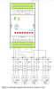
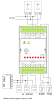
- Pt100 sensors connected by three wires to the IT-1604 module - ...ccordance with the following diagram. Fig. 1 An example of a three-wire connection of the Pt100 sensors to the IT-1604 module Notes: All sensors are powered via serial resistors (a 7k5 resistor, ideally wit...
- IT-1604, a module of universal analogue inputs - The IT-1604 expansion module has substituted the previous IT-1601 module. The module contains 8 analogue inputs with a common terminal and 2 analogue outputs with a common terminal. The inputs are universal, independently configurable as volta...
- Peripheral module address fixation on TCL2 - ...0100 - 05xx 3.8 a vyšší 2.8 * IT-1604 0400 a vyšší 0100 - 03xx 2.5 a vyšší...
- Power dissipation of modules for calculation of switchboard heating - ...les J, K, R, (S), B; 2xAO: 10 bit/±10V, GO IT-1602 2,5 W TXN 116 04 IT-1604, 8xAI: 16bit, 4-20mA, 0-10V, Ni1000, 2xAO: 10 bit/0÷10 V, GO IT-1604 4,5 W...
- MT-1691 submodule with resistors for powering passive sensors (for IT-1601) - ...ttom terminal block in accordance with Fig..3 and the free end of the wire should then be fastened in the A9 terminal of the IT-1604 module (like with the older IT-1601). The outlets of the MT-1691 resistive element should be inserted directly i...
- Measuring the dewing of a higher number of cooling ceilings, etc. - A solution for a high number of measuring points with the peripheral Foxtrot module IT-1604 . If it is necessary to monitor the dewing of ceilings in several rooms, the IT-1604 module can be used (with some added external resistors), to w...
- Error E-B1-88-1006 - ...What could cause this error? The TCL2 line is closed with the included resistor and connected in the proper bus structure. IT-1604 module is on the line. Thank you in advance!...
- Analog Input Module Capacity for Foxtrot 2 PLC - ...no limit for amount of analog modules on TCL2. The only limit is 10 IO modules on one TCL2 interface. Because analog module IT-1604 is equipped with 8 analog inputs, for 160 analog inputs you will need 2 fully occupied TCL2 buses. One on CP-2090 int...
- Analog input - ...(https://catalog.tecomat.cz/en/product/cp-200711ndnn#params) allow to connect 0 - 10 V signal. The same, peripheral modules IT-1604 (TCL2 bus) allow to connect all types of analog inputs - 0-10 V , 0 (4) - 20 mA, RTD (https://catalog.tecomat.cz/en/p...