


IT-1605TXN 116 05
IT-1605, 8xAI: 16bit, differential: thermocouples J, K, R, (S), B; 2xAO: 10 bit / 0 ÷ 10 V, GO
| DI | |
|---|---|
| DI/AI | |
| DO | |
| AI | 8x AI |
| AO | 2x AO |
| COM | 1x TCL2 |
| SENSOR |
| Picture | Variant | Variant description |
|---|---|---|

|
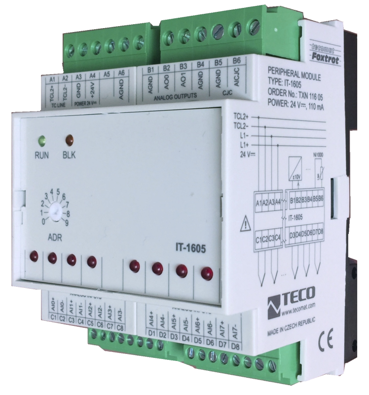
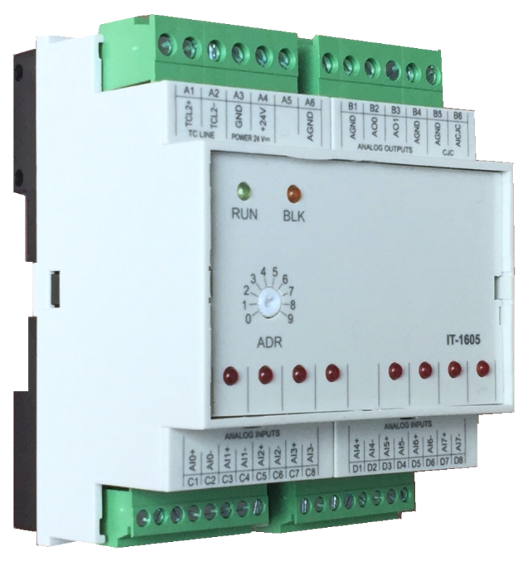
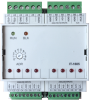
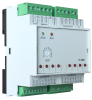
IT-1605 |
The expansion module IT-1605 contains 8 analog differencial inputs and 2 analog outputs with a common terminal. The inputs are universal, independently configurable as voltage inputs for low voltage or for the measuring of thermocouples. The resolution of inputs is 16 bits. The module ensures the measuring and the conversion of the measured value to the engineering units. Voltage analog outputs can be used in the range from -10 V to +10 V and the resolution is 10 bits. The inputs and outputs are galvanically separated from the power supply and TCL2 communication line. The status of each input is indicated by LEDs on the module. The module is equipped with removable screw-type terminals.
| Order num. | TXN 116 05 |
|---|---|
| Teco code | TXN 116 05 |
| Categories | Foxtrot - I / O Expansion Modules (TCL2) |
| Tags | - |
| AI - Organization of analog inputs | |
|---|---|
| Total number of analog inputs | 8 |
| Number of inputs per group | 8 |
| Number of analog input groups | 1 |
| Organization of analog inputs into groups | 8 (AI0-AI7) |
| Input type | Differential inputs |
| Common wire | AGND clamp |
| Galvanic separation from internal circuits | Yes, 8 inputs together |
| Diagnostics | overload signaling in status word |
| Type of protection | integrated overvoltage protections |
| External power supply | No |
| Digital resolution | 16 bit |
| The format of the data returned to the application program | see manual TXV 004 10 |
| Repeat time of sample | 400 ms max. |
| Total System Input Move Time (TAID + TAIT) | 100 ms max. |
| Operating modes | periodic input sensing |
| Filtration | low pass filter, digital comb filter 50/60 Hz |
| Insulation potential | 500 V DC between input and internal circuits |
| Analog input error - Steady state repeatability | 0.05% of full scale |
| AI - Analog Input Ranges (Group A) | |
| Voltage | ±1 V |
| Thermocouple | Type J (-210 ° C to 1200 ° C) |
| Thermocouple | Type K (–200 to +1372 ° C) |
| Thermocouple | Type R (-50 to +1768 ° C) |
| Thermocouple | Type N (-200 ° C ÷ 1300 ° C) |
| Thermocouple | Type T (-200 ° C ÷ 400 ° C) |
| Thermocouple | Type B (250 ° C ÷ 1820 ° C) |
| Thermocouple | Type S (-50 ° C ÷ 1768 °C) |
| Input impedance in the voltage signal range | > 1 MΩ |
| Voltage input error - max. error at 25 ° C | ± 0.5% of full scale |
| Voltage input error - temperature coefficient | ± 0,05% of full scale/K |
| Voltage input error - non-linearity | ± 0.1% of full scale |
| Voltage input error - repeatability under steady state conditions | 0.5% of full scale |
| Permissible continuous overload - voltage input | ± 20 V; each AI terminal against AGND |
| Total time of input transfer to system (TAID-TAIT) | < 100 ms |
| Sample repetition time | < 400 ms |
| AO - Analog output parameters | |
| Parameters valid for the terminals | AO0, AO1 |
| Output type | active voltage output |
| Converter resolution | 8 bit |
| conversion time | 10 μs |
| Analog output error - maximum error at 25 ° C | ± 2% of full scale |
| Analog output error - temperature coefficient | ± 0.3% of full scale / K |
| Analog output error - linearity | ± 0.7% of full scale |
| Analog output error - repeatability under steady state conditions | ± 0.5% of full scale |
| Voltage output - voltage | ±10,5 V |
| Voltage output - maximum output current | 10 mA |
| Insulation potentials under normal operating conditions | 500 V DC between output and internal circuits |
| Power supply | |
| Nominal supply voltage (V) | 24 V DC |
| Supply voltage, tolerances | 24 V DC, +25 %, –15 % |
| Module thermal/power loss | 2,7 W |
| Maximum current consumption (mA) | 110 mA |
| Galvanic separation of power supply from internal circuits | No |
| Internal protection | Yes, PTC reversible fuse |
| Size and weight | |
| Weight approx. | 150 g |
| Product dimensions (width x height x depth) | 52 x 90 x 58 mm |
| Module width in multiples of M (17.5 mm) | 3M |
| Operating conditions, product standards | |
| Product standard | ČSN EN 60730-1 ed.4 :2017 (EN 60730-1:2016) -Automatic electronic control device (for household and similar purposes) |
| Protection class of electrical object | I, according to ČSN EN 61140 ed.3: 2016 (idt IEC 61140:2016) |
| IP rating (Ingress Protection) according to ČSN EN 60529: 1993 (idt IEC 529: 1989) | IP20 |
| Operating areas | Normal, acc. ČSN 33 2000-1 ed.2: 2009 (mod IEC 60354-1:2005) |
| Degree of pollution | 1, according to ČSN EN 60664-1 ed.2:2008 ( idt IEC 60664-1:2007) |
| Overvoltage category installation | II, according to EN 60664-1 ed_2: 2008 (idt IEC 60641-1: 2007) |
| Type of device | Module on DIN rail |
| Working position | Vertical |
| Type of operation (operating frequency) | Continuous |
| Ambient operating temperatures | -10 °C to + 55 °C |
| Operating temperature maximum (° C) | +55°C |
| Operating temperature minimum (° C) | -10°C |
| Operating relative humidity | from 10 % up to 95 % without condensation |
| Operating atmospheric pressure | min. 70 kPa (<3,000 m above sea level) |
| Storage temperatures | –25 °C to +70 °C |
| Electromagnetic compatibility, Mechanical endurance | |
| Electromagnetic compatibility / Emission | A, according to EN 55032 ed. 2: 2017 (idt CISPR 32: 2015) |
| Emmisions - note | In premises where the use of radio and television receivers can be expected to be used a distance of 10 m from these devices may cause radio interference. In such a case, the user may be required to take appropriate action. |
| Electromagnetic compatibility / Immunity | min. as required by EN 61131-2: 2007 |
| Sinusoidal vibration endurance | 10 Hz to 57 Hz, amplitude 0,075 mm, 57 Hz to 150 Hz, acceleration 1 G (Fc test according to EN 60068-2-6: 1997 (idt IEC 68-2-6: 1995), 10 cycles per axis.) |
| Packaginng, transportation, storage | |
| Description |
The module is packed in a paper box. This documentation is also part of the package. The outer packaging is carried out according to the scope of the order and the method of transport in a transport package provided with labels and other data necessary for transport. The product must not be exposed to direct weather conditions during transport and storage. Malting of the product is only allowed in clean rooms without conductive dust, aggressive gases and vapors. The most suitable storage temperature is 20 ° C. |
| Installation | |
| Assembly description | Switchboard mounting |
| Assembly description | The peripheral module is mounted in a vertical position on the U-rail ČSN EN 50022. Installation of the assembly (basic module and possibly peripheral modules) is performed according to TXV 004 12 |
| Connection | |
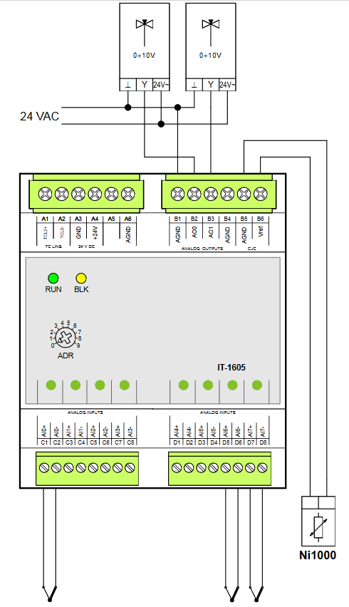
| Connection description |
Wiring notes: 1. The analog inputs and outputs are with a common AGND terminal. 2. It is recommended to use shielded wires to connect analog inputs and outputs. 3. The cold end sensor must be placed at the cold end connection point of the thermocouples. |
| Module operation | |
| Module configuration | The module is operated, set up and diagnosed from the Mosaic development environment. |
| Commissioning | The module is ready for operation after connecting the supply voltage. The address within the system is set on the panel (in the range 0 to 9). Other parameters are set in the MOSAIC programming environment. The exact setting procedure is given in the TXV 004 10 documentation. Further work is performed in the MOSAIC development environment. |
| Module diagnostics | The basic diagnostic system of the module is part of its standard software. It has been in operation since the module power was turned on and works independently of the user. Diagnosed module error states are listed in TXV 004 10. |
| Maintenance | |
| Description | The module does not require any maintenance under general installation conditions. The operations in which a part of the module has to be dismantled must always be carried out with the supply voltage disconnected. |
| Notice | Because the module contains semiconductor components, it is necessary to follow the principles for working with electrostatic sensitive components when handling the removed cover. It is not allowed to directly touch the printed circuit boards without protective measures !!! |
| Warranty | |
| Generally | Warranty and complaint conditions are governed by the Terms and Conditions of Teco a.s. |
| Notice | You must meet all the conditions of this documentation before turning on the system. The system must not be put into service unless it has been verified and confirmed that the machinery meets the requirements of Directive 89/392 / EEC, in so far as it applies to it. Documentation subject to change. |
HW documentation
IT-1605 - Basic documentation
1.05 MB, (EN)
Files for designers
Foxtrot 2 - library of elements in DXF and DWG formats, v. 2025/08.
21.80 MB
Foxtrot 2 - element library for SchemataCAD, v. 2025/08.
6.96 MB
EC - Declaration of Conformity
Foxtrot - EC Declaration of conformity
295.20 kB, (EN, RU, DE, UA)

- IT-1605, a module for the measurement of thermocouples and mV signals - The IT-1605 expansion module contains 8 analogue inputs with a common terminal and 2 analogue outputs with a common terminal. The inputs are universal and they can be configured independently as voltage inputs for small values or for measurement of...
- Peripheral module address fixation on TCL2 - ...0100 - 03xx 2.5 a vyšší 1.4 * IT-1605 všechny verze 1.8 a vyšší...
- Power dissipation of modules for calculation of switchboard heating - ...mA, 0-10V, Ni1000, 2xAO: 10 bit/0÷10 V, GO IT-1604 4,5 W TXN 116 05 IT-1605, 8xAI: 16bit, differential: thermocouples J, K, R, (S), B; 2xAO: 10 bit/0÷10 V, GO IT-1605 2...
- IT-1602 module for the measurement of thermocouples and mV signals - The module is not recommended for new installations, its successor is IT-1605 The IT-1602 expansion module contains 8 analogue inputs with a common terminal and 2 analogue outputs with a common terminal. The inputs are universal, independe...
- Measurement of high temperatures up to 1100 ° C, TC, C-IT-0200I - ...es can be measured with the C-IT-0200I module (see the following example), or we can use the analog input module IT-1605 (peripheral module of the Foxtrot system on the TCL2 bus), or with a smaller requirement for ac...
No data available.