


IR-1501TXN 115 01
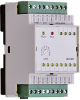
IR-1501, 4xDI 24 VAC / DC, 8xRO 230V / 2A, common terminal, galvanic isolation
| DI | 4x DI |
|---|---|
| DI/AI | |
| DO | 8x RO |
| AI | |
| AO | |
| COM | TCL2 |
| SENSOR |
| Picture | Variant | Variant description |
|---|---|---|

|
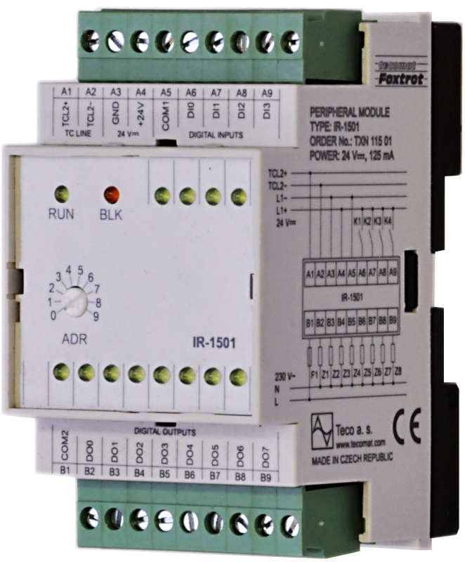
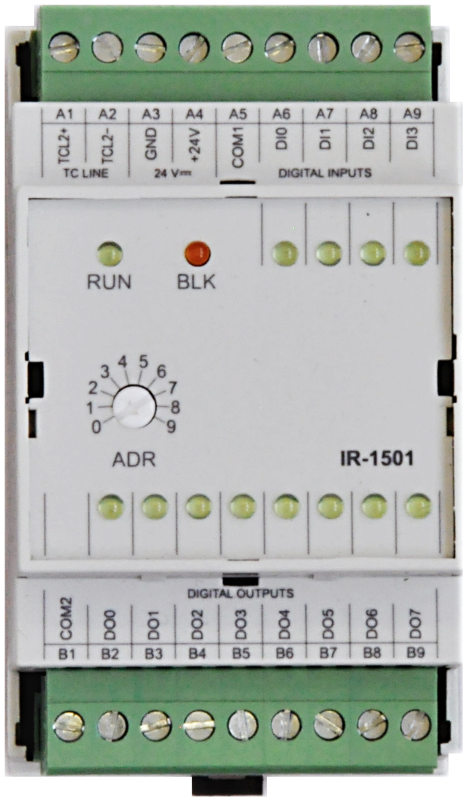
IR-1501 |
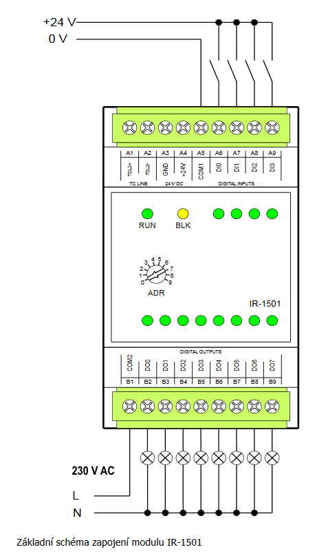
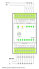
The IR-1501 expansion module is designed for reading up to 4 binary 24 V DC signals with a common terminal (according to the minus or plus connection), type 1 according to ČSN EN 61131.
The module contains 8 relay outputs with a switching contact and a common terminal.
The module is equipped with removable screw connectors.
Inputs DI0 ÷ DI3 allow to implement special functions identical to inputs DI0-DI3 of basic module CP-1004.
The relay outputs can switch max. 230 V AC, 3 A (current through the common terminal max. 10 A).
The inputs are galvanically isolated from the internal circuits (including power supply and communication) and the inputs are separated from the outputs.
The status of each input and output is indicated by an LED on the front panel of the module.
| Order num. | TXN 115 01 |
|---|---|
| Teco code | TXN 115 01 |
| Categories | Foxtrot - I / O Expansion Modules (TCL2) |
| Tags | - |
| COM - System buses | |
|---|---|
| TCL2 - system I/O bus | 1x TCL2 slave |
| TCL2 - Range of one branch of the system I/O bus | 10 I / O modules + 4 operator panels + 6 serial channels |
| DI - Parameters of binary inputs DC (group A) | |
| Parameters valid for inputs on the terminals | DI0-DI3 |
| Number of inputs in group | 4 |
| Common wire | plus |
| Input type | Type 1 (IEC) |
| Galvanic isolation of inputs from internal/peripheral circuits | Yes |
| Diagnostics | indication of energized input by LED on module panel |
| Input voltage for log. 0 | 0 V DC; -5 V DC min.; +5 V DC max. |
| Input voltage for log. 1 | 24 V DC; 15 V DC min.; 30 V DC max. |
| Input current at log. 1 (typ.) | 10 mA typ. |
| Delay from log. 1 to log. 0 | 5 μs |
| The minimum width of the captured pulse | 50 μs |
| HSC - Special functions of binary inputs / counters | |
| Unidirectional counter (UP) | 2x (DI0); (DI2) |
| Two unidirectional counters (UP / UPB) | 2x (DI0/DI2); (DI2/DI3) |
| Bidirectional counter (UP/DOWN) | 2x (DI0/DI1); (DI2/DI3) |
| Counter with direction control (CLK/DIR) | 2x (DI0/DI1); (DI2/DI3) |
| Bi-directional counter with reset and intercept (UP / DOWN / CLR / CAP) | 1x (DI0/DI1/DI2/DI3) |
| Counter with direction control with reset and latch (CLK / DIR / CLR / CAP) | 1x (DI0/DI1/DI2/DI3) |
| IRC Basic (V/G) | 2x (DI0/DI1); (DI2/DI3) |
| IRC with Zero and Capture (V / G / NI / MD) | 1x (DI0/DI1/DI2/DI3) |
| Measure the pulse length | 4x (DI0,DI1, DI2, DI3) |
| Period measurement | 4x (DI0,DI1, DI2, DI3) |
| HSC - Counter input parameters | |
| Counter: Input frequency / resolution | 5 kHz/1 pulse |
| Pulse width | min. 50 μs |
| Delay from log. 0 per log. 1 | 5 μs |
| Delay from log. 1 per log. 0 | 5 μs |
| Range of registers | up to 32 bits, 0 to 4 294 967 296 |
| HSC - Parameters of incremental encoder input (IRC) | |
| Frequency of symmetrical signal (V, G) | 1,25 kHz |
| Pulse Width (V, G, NI, MD) | min. 50 μs |
| Delay from log. 0 per log. 1 | 5 μs |
| Delay from log. 1 per log. 0 | 5 μs |
| Range of registers | up to 32 bits, 0 to 4 294 967 296 |
| HSC - Pulse length, period and phase shift measuring input parameters | |
| Input frequency | 0.1 to 5000 Hz |
| Pulse width | 50 μs to 10 s |
| Absolute measurement error | max. ±10 μs |
| RO - Parameters of binary relay outputs (group A) | |
| Number of relay outputs | 8 |
| Number of output groups | 1 |
| Number of outputs in group | 8 |
| Contact type | NO - Normally Open |
| Diagnose | Alarm signaling on panel module |
| Switching current | 3 A max., 100 mA min. |
| Switching voltage | 250 V AC max., 5 V AC min., 30V DC max. |
| Short-term output overload - inrush | 4 A max. |
| Current through common clamp | 10 A max. |
| Contact closing time | typ. 10 ms |
| Contact opening time | typ. 4 ms |
| Limit values of switched resistive load | max. 3A at 30 V DC or 230 V AC |
| Switching inductive load limits DC13 | max. 3 A at 30 V DC |
| Switching inductive load limits AC15 | max. 3 A at 230 V AC |
| Switching frequency with rated load | max. 20 switching / min. |
| Mechanical life | min. 5,000,000 cycles |
| Electrical life at maximum resistive load | min. 100,000 cycles |
| Electrical life at maximum load inductive DC13 | min. 100,000 cycles |
| Electrical life at maximum load inductive AC15 | min. 100,000 cycles |
| Short-circuit protection | No |
| Treatment of inductive load | External RC element, varistor (AC), diode (DC) |
| Insulation voltage between outputs and internal circuits | 3750 V AC |
| Power supply | |
| Nominal supply voltage (V) | 24 V DC |
| Typical power input | 2 W |
| Maximum power input | 3 W |
| Module thermal/power loss | 3 W |
| Maximum current consumption (mA) | 90 mA |
| Galvanic separation of power supply from internal circuits | No |
| Internal protection | Yes, PTC reversible fuse |
| Size and weight | |
| Weight approx. | 150 g |
| Product dimensions (width x height x depth) | 52 x 90 x 58 mm |
| Module width in multiples of M (17.5 mm) | 3M |
| Operating conditions, product standards | |
| Product standard | ČSN EN 61131-2: 2005 (idt IEC61131-2: 2003) - Programmable control units |
| Protection class of electrical object | III, according to ČSN EN 61140 ed.3: 2016 (idt IEC 61140:2016) |
| IP rating (Ingress Protection) according to ČSN EN 60529: 1993 (idt IEC 529: 1989) | IP20 |
| Operating areas | Normal, acc. ČSN 33 2000-1 ed.2: 2009 (mod IEC 60354-1:2005) |
| Degree of pollution | 1, according to ČSN EN 60664-1 ed.2:2008 ( idt IEC 60664-1:2007) |
| Overvoltage category installation | II, acc. ČSN EN 60664-1:2004 (mod IEC 606641:1992) |
| Type of device | Module on DIN rail |
| Working position | Vertical |
| Type of operation (operating frequency) | Continuous |
| Ambient operating temperatures | 0 ° C to + 55 ° C |
| Operating temperature maximum (° C) | +55°C |
| Operating temperature minimum (° C) | 0°C |
| Operating relative humidity | from 10 % up to 95 % without condensation |
| Operating atmospheric pressure | min. 70 kPa (<3,000 m above sea level) |
| Storage temperatures | –25 °C to +70 °C |
| Electromagnetic compatibility, Mechanical endurance | |
| Electromagnetic compatibility / Emission | A, according to EN 55022: 1999 (mod CISPR22: 1997) |
| Emmisions - note | In premises where the use of radio and television receivers can be expected to be used a distance of 10 m from these devices may cause radio interference. In such a case, the user may be required to take appropriate action. |
| Electromagnetic compatibility / Immunity | min. as required by EN 61131-2: 2007 |
| Sinusoidal vibration endurance | 10 Hz to 57 Hz, amplitude 0,075 mm, 57 Hz to 150 Hz, acceleration 1 G (Fc test according to EN 60068-2-6: 1997 (idt IEC 68-2-6: 1995), 10 cycles per axis.) |
| Packaginng, transportation, storage | |
| Description | The module is packed in a paper box. This documentation is also part of the package. The outer packaging is carried out according to the scope of the order and the method of transport in a transport package provided with labels and other data necessary for transport. The product must not be exposed to direct weather conditions during transport and storage. Malting of the product is only allowed in clean rooms without conductive dust, aggressive gases and vapors. The most suitable storage temperature is 20 ° C |
| Installation | |
| Assembly description | The module is mounted in a vertical position on the U-rail ČSN EN 50022. Installation of the assembly (basic module and possibly peripheral modules) is performed according to TXV 004 13. |
| Connection | |
| Connection of power and system communication | connector with 2.5 mm2 screw terminal |
| Connection of inputs / outputs | connector with screw terminal 2.5 mm2 |
| Module operation | |
| Module configuration | The module is operated, set up and diagnosed from the Mosaic development environment. |
| Commissioning | The module is ready for operation after connecting the supply voltage. The address within the system is set on the module panel (in the range 0 to 9). Other parameters are set in the Mosaic programming environment. The exact setting procedure is given in the TXV 004 12 documentation. Further action is performed in the MOSAIC development environment. |
| Module diagnostics | The basic diagnostic system of the module is a part of its standard software. It operates from module power on and operates independently of the user. Diagnostic error states of the module and connected peripheral modules of the assembly are signaled |
| Maintenance | |
| Description | The module does not require any maintenance under general installation conditions. The operations in which a part of the module has to be dismantled must always be carried out with the supply voltage disconnected. |
| Notice | Because the module contains semiconductor components, it is necessary to follow the principles for working with electrostatic sensitive components when handling the removed cover. It is not allowed to directly touch the printed circuit boards without protective measures !!! |
| Warranty | |
| Generally | Warranty and complaint conditions are governed by the Terms and Conditions of Teco a.s. |
| Notice | You must meet all the conditions of this documentation before turning on the system. The system must not be put into service unless it has been verified and confirmed that the machinery meets the requirements of Directive 89/392 / EEC, in so far as it applies to it. Documentation subject to change. |
HW documentation
IR-1501 - Basic Documentation
1.21 MB, (EN)
Files for designers
Foxtrot 2 - library of elements in DXF and DWG formats, v. 2025/08.
21.80 MB
Foxtrot 2 - element library for SchemataCAD, v. 2025/08.
6.96 MB
EC - Declaration of Conformity
Foxtrot - EC Declaration of conformity
295.20 kB, (EN, RU, DE, UA)
- IR-1501, the module of relay outputs - The IR-1501 expansion module is designed to scan up to four 24 VDC binary signals with a common terminal (plus or minus, according to the wiring), type 1. The module contains 8 relay outputs with a switching contact and a common terminal. &nbs...
- Peripheral module address fixation on TCL2 - ...0100 - 05xx 3.8 a vyšší 2.8 * IR-1501 0600 a vyšší 0100 - 05xx 3.8 a vyšší...
- Power dissipation of modules for calculation of switchboard heating - ...OS-1401, 12xDO 24 VDC, 8x 0.5A, 4x 2A, GO OS-1401 2,5 W TXN 115 01 IR-1501, 4xDI 24 VAC/DC, 8xRO, common terminal, 230V/2A, GO IR-1501 3,5 W TXN 116 02...
- The 6 A relays, the Foxtrot peripheral modules - These relays are fitted e.g. in the IR-1501 Foxtrot peripheral modules. Tab. 1. The parameters of the actual relay contact (each specific module can have different values!) Nominal current...
No data available.