
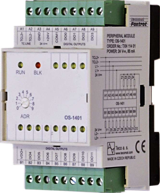
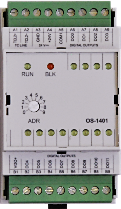
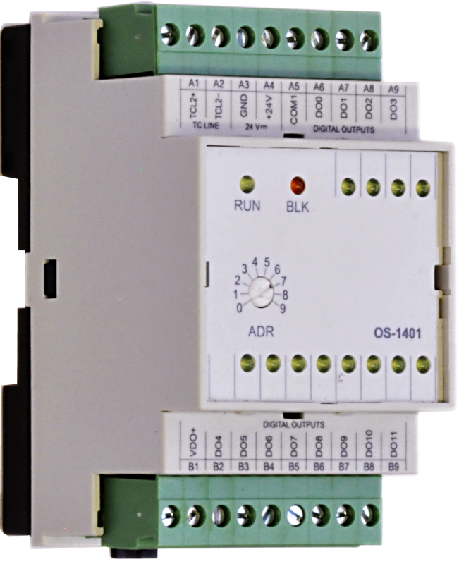
OS-1401TXN 114 01
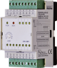
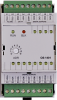
OS-1401,12xDO 24 VDC, common pole, 8x0.5A, 4x 2A GO
| DI | |
|---|---|
| DI/AI | |
| DO | 12x DO |
| AI | |
| AO | |
| COM | 1x TCL2 slave |
| SENSOR |
| Picture | Variant | Variant description |
|---|---|---|

|
OS-1401 |
The IB-1301 expansion module is designed for the scanning of up to 12 binary signals 24 V DC with a common pole (minus or plus to way of connection), type 1 according to ČSN EN 61131. The module is equipped with removable screw-type connector. Inputs DI0 to DI3 allow to carry out a special functions conform to inputs on CP-1004 basic module. The inputs are galvanically isolated from the internal circuits (including power supply and communication) and groups of inputs are separated one from another. The status of each input is indicated by LED at the front module panel.
| Order num. | TXN 114 01 |
|---|---|
| Teco code | TXN 114 01 |
| Categories | Foxtrot - I / O Expansion Modules (TCL2) |
| Tags | - |
| COM - System buses | |
|---|---|
| TCL2 - system I/O bus | 1x TCL2 slave |
| DO/RO - Organization of binary outputs | |
| Total number of binary outputs | 12 |
| Organization of binary outputs into groups | 4 (DO0-DO3) + 8 (DO4-DO11) |
| DO - Parameters of binary transistor outputs (group A) | |
| Parameters valid for the terminals | DO0-DO3 |
| Number of output groups | 2 |
| Common group conductor | plus |
| Output type | transistor output |
| Galvanic separation from internal circuits | Yes |
| Diagnostics | indication of energized output by LED on module panel |
| Switching voltage | 9,6 - 28.8 V DC |
| Switching current, output load | 2 A max. |
| Group current | 2,5 A max. |
| Switching time | 400 μs max. |
| Opening time | 400 μs max. |
| Residual current | 300 μA max. |
| Short circuit protection | Yes |
| Short-circuit current limitation | typ. 4 A |
| Treatment of inductive load | External RC element, varistor (AC), diode (DC) |
| Reverse polarity protection | Yes - The circuit will be inactive, the loads will be closed, current will flow through the protection diodes of the circuit. |
| Initial peak current limitation | typ. 7,5 A |
| DO - Parameters of binary transistor outputs (group B) | |
| Parameters valid for the terminals | DO4-DO11 |
| Number of transistor outputs | 8 |
| Common group conductor | plus |
| Output type | transistor output |
| Galvanic separation from internal circuits | Yes |
| Diagnostics | indication of energized output by LED on module panel |
| Switching current, output load | 0,5A max. |
| Group current | 4 A max. |
| Switching time | 400 μs max. |
| Opening time | 400 μs max. |
| Residual current | 300 μA max. |
| Short circuit protection | Yes - electronic |
| Short-circuit current limitation | typ. 4 A |
| Treatment of inductive load | External RC element, varistor (AC), diode (DC) |
| Reverse polarity protection | Yes - The circuit will be inactive, the loads will be closed, current will flow through the protection diode of the circuit. |
| Initial peak current limitation | typ. 7,5 A |
| Initial peak current tripping time | typ. 4 ms |
| Power supply | |
| Nominal supply voltage (V) | 24 V DC |
| Typical power input | 1 W |
| Maximum power input | 2 W |
| Module thermal/power loss | 2,5 W |
| Maximum current consumption (mA) | 100 mA |
| Galvanic separation of power supply from internal circuits | No |
| Internal protection | Yes, PTC reversible fuse |
| Size and weight | |
| Weight approx. | 100 g |
| Product dimensions (width x height x depth) | 52 x 90 x 58 mm |
| Module width in multiples of M (17.5 mm) | 3M |
| Operating conditions, product standards | |
| Product standard | ČSN EN 61131-2:2008 (idt IEC 61131-2:2007) - Programmable control units |
| Protection class of electrical object | III, according to ČSN EN 61140 ed.3: 2016 (idt IEC 61140:2016) |
| IP rating (Ingress Protection) according to ČSN EN 60529: 1993 (idt IEC 529: 1989) | IP20 |
| Operating areas | Normal, acc. ČSN 33 2000-1 ed.2: 2009 (mod IEC 60354-1:2005) |
| Degree of pollution | 1, according to ČSN EN 60664-1 ed.2:2008 ( idt IEC 60664-1:2007) |
| Overvoltage category installation | II, acc. ČSN EN 60664-1:2004 (mod IEC 606641:1992) |
| Type of device | Module on DIN rail |
| Type of operation (operating frequency) | Continuous |
| Ambient operating temperatures | 0 ° C to + 55 ° C |
| Operating temperature minimum (° C) | 0°C |
| Operating relative humidity | from 10 % up to 95 % without condensation |
| Operating atmospheric pressure | min. 70 kPa (<3,000 m above sea level) |
| Storage temperatures | –25 °C to +70 °C |
| Electromagnetic compatibility, Mechanical endurance | |
| Electromagnetic compatibility / Emission | A, according to EN 55022: 1999 (mod CISPR22: 1997) |
| Emmisions - note | In premises where the use of radio and television receivers can be expected to be used a distance of 10 m from these devices may cause radio interference. In such a case, the user may be required to take appropriate action. |
| Electromagnetic compatibility / Immunity | min. as required by EN 61131-2: 2007 |
| Sinusoidal vibration endurance | 10 Hz to 57 Hz, amplitude 0,075 mm, 57 Hz to 150 Hz, acceleration 1 G (Fc test according to EN 60068-2-6: 1997 (idt IEC 68-2-6: 1995), 10 cycles per axis.) |
| Packaginng, transportation, storage | |
| Description | The module is packed in a paper box. This documentation is also part of the package. The outer packaging is carried out according to the scope of the order and the method of transport in a transport package provided with labels and other data necessary for transport. The product must not be exposed to direct weather conditions during transport and storage. Malting of the product is only allowed in clean rooms without conductive dust, aggressive gases and vapors. The most suitable storage temperature is 20 ° C |
| Installation | |
| Assembly description | Module is mounted in a vertical position on the U-rail ČSN EN 50022. Assembly installation (basic module and possibly peripheral modules) is performed according to TXV 004 10.01. |
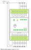
| Connection | |
| Connection of power and system communication | connector with 2.5 mm2 screw terminal |
| Connection of inputs / outputs | connector with screw terminal 2.5 mm2 |
| Module operation | |
| Module configuration | The module is operated, set up and diagnosed from the Mosaic development environment. |
| Commissioning | The module is ready for operation after connecting the supply voltage. The MODE button is available on the module panel to display the currently set Ethernet IP address. The parameters of all interfaces are set in the Mosaic development environment. |
| Module diagnostics | The basic diagnostic system of the module is a part of its standard software. It operates from module power on and operates independently of the user. Diagnostic error states of the module and connected peripheral modules of the assembly are signaled |
| Maintenance | |
| Description | The module does not require any maintenance under general installation conditions. The operations in which a part of the module has to be dismantled must always be carried out with the supply voltage disconnected. |
| Notice | Because the module contains semiconductor components, it is necessary to follow the principles for working with electrostatic sensitive components when handling the removed cover. It is not allowed to directly touch the printed circuit boards without protective measures !!! |
| Warranty | |
| Generally | Warranty and complaint conditions are governed by the Terms and Conditions of Teco a.s. |
| Notice | You must meet all the conditions of this documentation before turning on the system. The system must not be put into service unless it has been verified and confirmed that the machinery meets the requirements of Directive 89/392 / EEC, in so far as it applies to it. Documentation subject to change. |
HW documentation
OS-1401 - Basic documentation
1.24 MB, (EN)
Files for designers
Foxtrot 2 - library of elements in DXF and DWG formats, v. 2025/08.
21.80 MB
Foxtrot 2 - element library for SchemataCAD, v. 2025/08.
6.96 MB
EC - Declaration of Conformity
Foxtrot - EC Declaration of conformity
295.20 kB, (EN, RU, DE, UA)
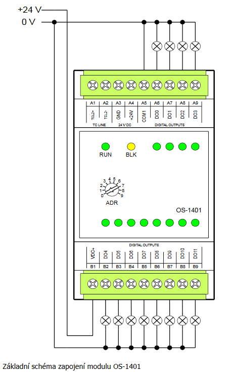
- OS-1401, the module of 24V binary outputs - The OS-1401 expansion module contains 12 semiconductor outputs with a switching contact and a common positive terminal (VDO+). The DO0 ÷ DO3 outputs allow switching max. 24 VDC, 2 A per output (total current load of all four outputs mu...
- Peripheral module address fixation on TCL2 - ...0100 - 05xx 3.8 a vyšší 2.8 * OS-1401 0600 a vyšší 0100 - 05xx 3.8 a vyšší...
- Power dissipation of modules for calculation of switchboard heating - ...TXN 113 01 IB-1301, 12xDI 24 VAC/DC, GO IB-1301 3,0 W TXN 114 01 OS-1401, 12xDO 24 VDC, 8x 0.5A, 4x 2A, GO OS-1401 2,5 W TXN 115 01 IR-1501,...
No data available.