


OT-1651TXN 116 51
OT-1651, 4xAO: 0-10V/ 4-20mA, GO
| DI | |
|---|---|
| DI/AI | |
| DO | |
| AI | |
| AO | 4x AO (0-20mA/0-10V) |
| COM | TCL2 |
| SENSOR |
| Picture | Variant | Variant description |
|---|---|---|

|
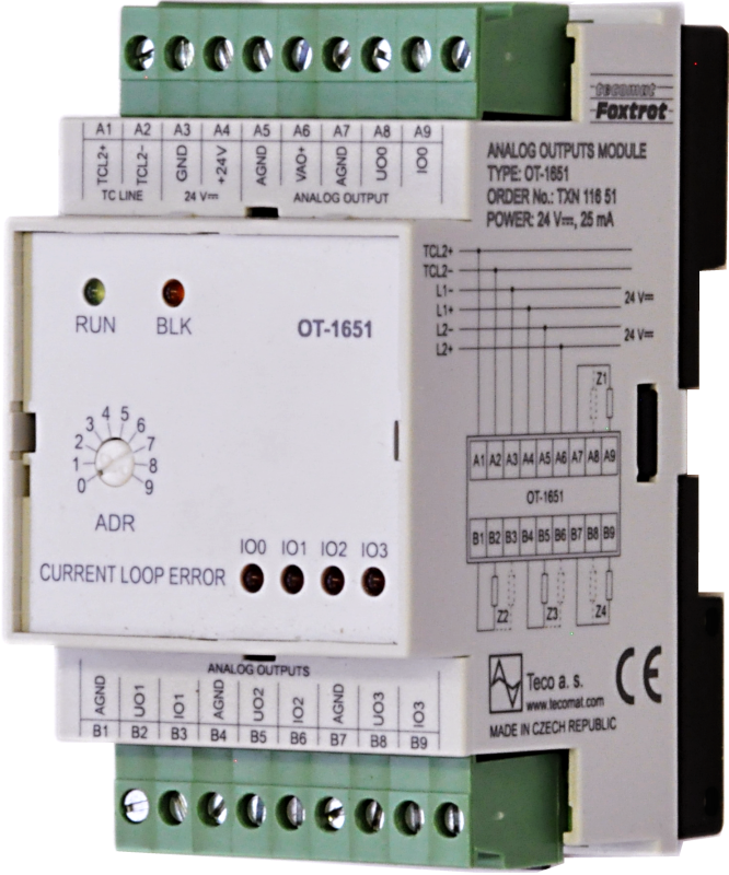
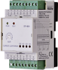
OT-1651 |
The OT-1651 expansion module contains 4 analog unipolar outputs.
Either voltage or current output can be used. Loads of both types are connected to the ground.
The resolution is 12 bits, the value can be set as a percentage of the maximum value, engineering unit or fulscale (0-30000).
The analog outputs are galvanically separated from the input voltage of the processor part, TCL2 communication and internal circuits.
They have a separate power supply. The status of the current loop is signaled on the module panel.
The module is equipped with removable screw connectors.
| Order num. | TXN 116 51 |
|---|---|
| Teco code | TXN 116 51 |
| Categories | Foxtrot - I / O Expansion Modules (TCL2) |
| Tags | - |
| COM - System buses | |
|---|---|
| TCL2 - system I/O bus | 1x TCL2 slave |
| AO - Analog output parameters | |
| The number of groups of analogue outputs | 1 |
| Number of outputs in group | 4 |
| Number of outputs and their organization into groups | 4x AO (UO0/IO0-UO3/IO1) |
| Parameters valid for the terminals | UO0/IO0 - UO3/IO3 |
| Common wire of group | AGND terminal |
| Galvanic isolation from internal circuits | No |
| Output type | active voltage output |
| Disconnected output detection | Yes current loop from 0.1 mA |
| Overload signaling | No |
| Max. permissible permanent overload (without damage) | (-1 V) to (+ Vao + 1V) each terminal against AGND |
| Converter resolution | 12 bit |
| Analog output error - maximum error at 25 ° C | ± 0.3% of full scale |
| Output repeat setting time | typ. 0,5 ms |
| Analog output error - temperature coefficient | ± 0.05% of full scale/K |
| Analog output error - linearity | ± 0.1% of full scale |
| Analog output error - repeatability under steady state conditions | ± 0.5% of full scale |
| External power supply | typ. 24 V DC |
| External power supply - tolerance | - 25 ÷ +20% |
| External power supply - max. Current consumption | 135 mA |
| Voltage output - voltage | ±10,5 V |
| Voltage output - maximum output current | 10 mA |
| Voltage output - short-circuit output current | 12 mA |
| Current output - range | 0 ÷ 20 mA |
| Current output - current loop resistance | 0 ÷ 600 Ω |
| Power supply | |
| Nominal supply voltage (V) | 24 V DC |
| Supply voltage, tolerances | 24 V DC, +25 %, –15 % |
| Typical power input | 1 W |
| Maximum power input | 4,5 W |
| Module thermal/power loss | 4,5 W |
| Galvanic separation of power supply from internal circuits | No |
| Internal protection | No |
| Size and weight | |
| Weight approx. | 125 g |
| Product dimensions (width x height x depth) | 52 x 90 x 58 mm |
| Module width in multiples of M (17.5 mm) | 3M |
| Operating conditions, product standards | |
| Product standard | ČSN EN 61131-2:2008 (idt IEC 61131-2:2007) - Programmable control units |
| Protection class of electrical object | II, according to ČSN EN 61140 ed.3: 2016 (idt IEC 61140:2016) |
| IP rating (Ingress Protection) according to ČSN EN 60529: 1993 (idt IEC 529: 1989) | IP20 |
| Operating areas | Normal, acc. ČSN 33 2000-1 ed.2: 2009 (mod IEC 60354-1:2005) |
| Degree of pollution | 1, according to ČSN EN 60664-1 ed.2:2008 ( idt IEC 60664-1:2007) |
| Overvoltage category installation | II, according to EN 60664-1 ed_2: 2008 (idt IEC 60641-1: 2007) |
| Type of device | Module on DIN rail |
| Working position | Vertical |
| Type of operation (operating frequency) | Continuous |
| Ambient operating temperatures | -20 °C to + 55 °C |
| Storage temperatures | –25 °C to +70 °C |
| Electromagnetic compatibility, Mechanical endurance | |
| Electromagnetic compatibility / Emission | A, according to EN 55032 ed. 2: 2017 (idt CISPR 32: 2015) |
| Emmisions - note | In premises where the use of radio and television receivers can be expected to be used a distance of 10 m from these devices may cause radio interference. In such a case, the user may be required to take appropriate action. |
| Electromagnetic compatibility / Immunity | min. as required by EN 61131-2: 2007 |
| Sinusoidal vibration endurance | 10 Hz to 57 Hz, amplitude 0,075 mm, 57 Hz to 150 Hz, acceleration 1 G (Fc test according to EN 60068-2-6: 1997 (idt IEC 68-2-6: 1995), 10 cycles per axis.) |
| Packaginng, transportation, storage | |
| Description |
The module is packed in a paper box according to the internal packing instructions. This documentation is also part of the package. The outer packaging is carried out according to the scope of the order and the method of transport in a transport package provided with transport labels and other data necessary for transport. Transport from the manufacturer is carried out in the manner agreed upon when ordering. The transport of the product by the customer's own means must be carried out by covered means of transport, in the position determined by the label on the packaging. The box must be stored in such a way that it does not move spontaneously and the outer packaging is not damaged. The product must not be exposed to direct weather conditions during transport and storage. Transport is permitted at temperatures of -25 ° C to 70 ° C, relative humidity of 10% to 95% (non-condensing) and a minimum atmospheric pressure higher than 70 kPa. The product may only be stored in clean rooms free of conductive dust, aggressive gases and vapors. The most suitable storage temperature is 20 ° C. |
| Installation | |
| Assembly description | The basic module is mounted in a vertical position on the U-rail ČSN EN 50022. The installation of the assembly (basic module and possibly peripheral modules) is performed according to TXV 004 10. |
| Connection | |
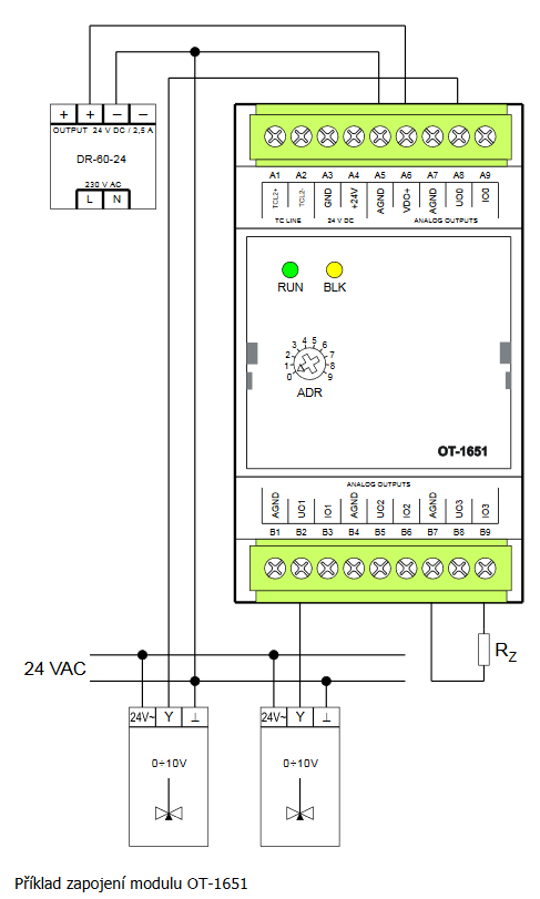
| Connection description |
Wiring notes: 1. The analog output can be used on either channel either voltage or current, not both at the same time. 2. In the connection example, 2 ways of load connection are shown. They can be combined with each other. 3. The selection of the analog output type is performed in the Mosaic environment. 4. It is recommended to use shielded wires to connect the analog outputs. 5. Voltage for analog outputs can be changed according to the table of electrical parameters (chapter 1.3) |
| Connection of power and system communication | connector with 2.5 mm2 screw terminal |
| Connection of inputs / outputs | connector with screw terminal 2.5 mm2 |
| Module operation | |
| Module configuration | The module is operated, set up and diagnosed from the Mosaic development environment. |
| Commissioning | The module is ready for operation after connecting the supply voltage. The MODE button is available on the module panel to display the currently set Ethernet IP address. The parameters of all interfaces are set in the Mosaic development environment. |
| Module diagnostics | The basic diagnostic system of the module is part of its standard software. It has been in operation since the module power was turned on and works independently of the user. Diagnosed module error states are listed in TXV 004 10. |
| Maintenance | |
| Description | The module does not require any maintenance under general installation conditions. The operations in which a part of the module has to be dismantled must always be carried out with the supply voltage disconnected. |
| Notice | Because the module contains semiconductor components, it is necessary to follow the principles for working with electrostatic sensitive components when handling the removed cover. It is not allowed to directly touch the printed circuit boards without protective measures !!! |
| Warranty | |
| Generally | Warranty and complaint conditions are governed by the Terms and Conditions of Teco a.s. |
| Notice | You must meet all the conditions of this documentation before turning on the system. The system must not be put into service unless it has been verified and confirmed that the machinery meets the requirements of Directive 89/392 / EEC, in so far as it applies to it. Documentation subject to change. |
HW documentation
OT-1651 - Basic documentation
1.17 MB, (EN)
Files for designers
Foxtrot 2 - library of elements in DXF and DWG formats, v. 2025/08.
21.80 MB
Foxtrot 2 - element library for SchemataCAD, v. 2025/08.
6.96 MB
EC - Declaration of Conformity
Foxtrot - EC Declaration of conformity
295.20 kB, (EN, RU, DE, UA)
- OT-1651, a module with 4 analogue outputs - The OT-1651 expansion module contains four unipolar analogue outputs. Each can be used either as a voltage or a current output. Both types of loads are connected against the common terminal - signal ground (AGND). The resolution is 12 bits. The ana...
- Peripheral module address fixation on TCL2 - ...605 všechny verze 1.8 a vyšší OT-1651 0200 a vyšší 0100 - 01xx 2.4 a vyšší...
- Power dissipation of modules for calculation of switchboard heating - ...s J, K, R, (S), B; 2xAO: 10 bit/0÷10 V, GO IT-1605 2,7 W TXN 116 51 OT-1651, 4xAO: 0-10V/ 4-20mA, GO OT-1651 4,5 W TXN 117 01 IC-1701, 8x DI fa...
No data available.