
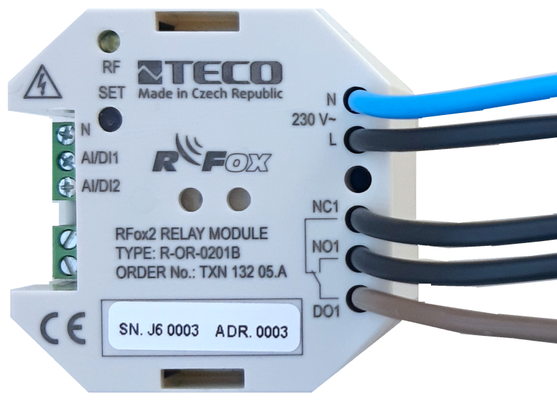
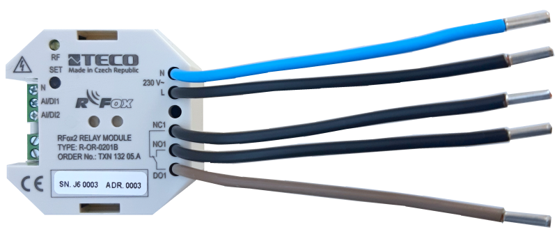
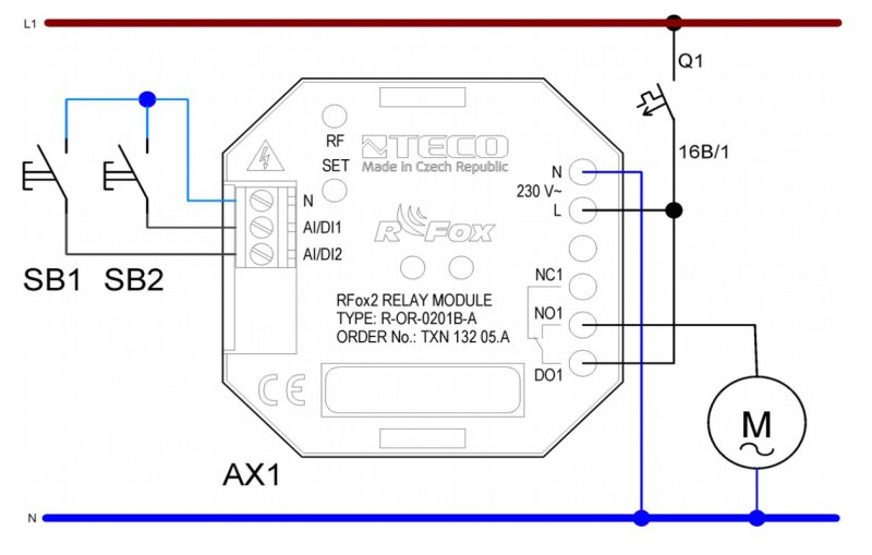


R-OR-0201B-A, relay moduleTXN 132 05.A
R-OR-0201B-A; RFox2, 2x DI, 1x RO-800A NO contact, radio type A
| DI | |
|---|---|
| DI/AI | 2x DI/AI |
| DO | 1x RO |
| AI | |
| AO | |
| COM | |
| SENSOR |
| Picture | Variant | Variant description |
|---|---|---|

|
R-OR-0201B-A, relay module |
R-OR-0201B-A; RFox2, 2x DI, 1x RO-800A NO contact, radio type A
| Order num. | TXN 132 05.A |
|---|---|
| Teco code | TXN 132 05.A |
| Categories | RFox2 - Built-in Modules |
| Tags | - |
| COM - Wireless network | |
|---|---|
| RFox2 wireless network | RFox2 Slave |
| Communication frequency band | 868,1 MHz |
| Transmission power | +14 dBm |
| Input sensitivity | –108 dBm |
| Modulation type | 2-GFSK |
| Communication speed | 50 kbps |
| DI - Parameters of binary inputs DC (group A) | |
| Parameters valid for inputs on the terminals | AI/DI1, AI/DI2 |
| Number of inputs in group | 2 |
| Common wire | minus |
| Combined input type | DI/AI Active, for sensing potential-free contacts and measuring resistance sensors |
| Galvanic isolation of inputs from internal/peripheral circuits | No |
| Max. measuring voltage on the connected contact | 3,3 V DC |
| Internal input resistance | 4,7 kΩ |
| RO - Parameters of binary relay outputs (group A) | |
| Parameters valid for the terminals | DO1, NC1, NO1 |
| Number of relay outputs | 1 |
| Number of output groups | 1 |
| Number of outputs in group | 1 |
| Organization of relay outputs into groups | 1x (DO1, NC1, NO1) |
| Output type | electromechanical relay, unprotected output |
| Switching voltage | 300 V max., 5 V min. |
| Mechanical life | min. 20 000 000 cycles |
| Electrical life at maximum load inductive DC13 | min. 50,000 cycles |
| Short-circuit protection | No |
| Treatment of inductive load | External RC element, varistor (AC), diode (DC) |
| Insulation voltage between outputs and internal circuits | 4000 V AC |
| Isolation voltage between groups of outputs to each other | 4000 V AC |
| AI - Analog Input Ranges (Group A) | |
| Voltage | 0-3,3 V |
| Passive sensor | Resistance transmitter 0-15 kOhm |
| Passive sensor | NTC Thermistor 12k / 25 °C (-40 to + 125 °C) |
| Power supply | |
| Nominal supply voltage (V) | 230 V AC |
| Typical power input | 3 W |
| Maximum power input | 4,5 W |
| Maximum current consumption (mA) | < 20 mA |
| Galvanic separation of power supply from internal circuits | No |
| Internal protection | No |
| Size and weight | |
| Product dimensions (width x height x depth) | 50 × 50 × 27 mm |
| Operating conditions, product standards | |
| Product standard | ČSN EN 61131-2:2008 (idt IEC 61131-2:2007) - Programmable control units |
| Protection class of electrical object | II, according to ČSN EN 61140 ed.3: 2016 (idt IEC 61140:2016) |
| IP rating (Ingress Protection) according to ČSN EN 60529: 1993 (idt IEC 529: 1989) | IP20 |
| Operating areas | Normal, acc. ČSN 33 2000-1 ed.2: 2009 (mod IEC 60354-1:2005) |
| Degree of pollution | 1, according to ČSN EN 60664-1 ed.2:2008 ( idt IEC 60664-1:2007) |
| Overvoltage category installation | I, according to ČSN EN 60664-1 ed_2:2008 (idt IEC 60641-1:2007) |
| Type of device | In the installation box, under the cover |
| Working position | marked on the cover |
| Type of operation (operating frequency) | Continuous |
| Ambient operating temperatures | -20 °C to + 55 °C |
| Operating relative humidity | from 10 % up to 95 % without condensation |
| Operating atmospheric pressure | min. 70 kPa (<3,000 m above sea level) |
| Storage temperatures | –25 °C to +70 °C |
| Electromagnetic compatibility, Mechanical endurance | |
| Electromagnetic compatibility / Emission | B, according to EN 55032 ed. 2: 2017 (idt CISPR 32: 2015) |
| Electromagnetic compatibility / Immunity | min. as required by EN 61131-2: 2007 |
| Sinusoidal vibration endurance | 10 Hz to 57 Hz, amplitude 0,075 mm, 57 Hz to 150 Hz, acceleration 1 G (Fc test according to EN 60068-2-6: 1997 (idt IEC 68-2-6: 1995), 10 cycles per axis.) |
| Connection | |
| Connection description | Klemmenblock, Leiter max. 1,5 mm2 und Leiter 2,5 mm2 |
| Module operation | |
| Commissioning | The module is operated, set and diagnosed from the MOSAIC programming environment. The module is ready for operation after connecting the supply voltage. The HW address is indicated on the label on the front panel. |
| Module diagnostics | The basic diagnostics is performed internally and the result is available in the relevant registers of the Mosaic environment. |
| Maintenance | |
| Description | The module does not require any maintenance under general installation conditions. The operations in which a part of the module has to be dismantled must always be carried out with the supply voltage disconnected. |
| Warning | Because the module contains semiconductor components, it is necessary to follow the principles for working with electrostatic sensitive components when handling the removed cover. It is not allowed to directly touch the printed circuit boards without protective measures. |
| Warranty | |
| Generally | Warranty and complaint conditions are governed by the Terms and Conditions of Teco a.s. |
| Notice | You must meet all the conditions of this documentation before turning on the system. The system must not be put into service unless it has been verified and confirmed that the machinery meets the requirements of Directive 89/392 / EEC, in so far as it applies to it. Documentation subject to change. |
HW documentation
R-OR-0201B-A - Basic documentation
197.64 kB
Files for designers
Foxtrot 2 - library of elements in DXF and DWG formats, v. 2025/08.
21.80 MB
Foxtrot 2 - element library for SchemataCAD, v. 2025/08.
6.96 MB
No data available.
No data available.