
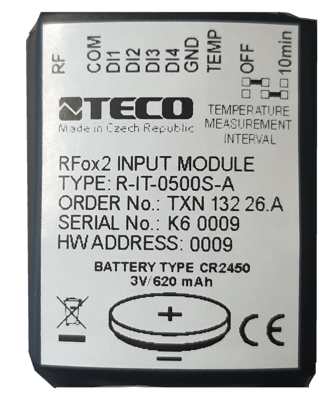


R-IT-0500S-A, contacts, temperatureTXN 132 26.A
R-IT-0500S-A; RFox2, 4x DI dry contact, 1x temperature, battery, radio type A
| DI | 4x DI |
|---|---|
| DI/AI | |
| DO | |
| AI | 1x temperature |
| AO | |
| COM | 1x RFox2 slave |
| SENSOR |
| Picture | Variant | Variant description |
|---|---|---|

|
R-IT-0500S-A, contacts, temperature |
R-IT-0500S-A; RFox2; 4x DI dry contact, 1x temperature, battery, radio type A
| Order num. | TXN 132 26.A |
|---|---|
| Teco code | TXN 132 26.A |
| Categories | RFox2 - Built-in Modules |
| Tags | - |
| COM - Wireless network | |
|---|---|
| RFox2 wireless network | RFox2 Slave |
| Communication frequency band | 868,1 MHz |
| Transmission power | +14 dBm |
| Input sensitivity | –108 dBm |
| Modulation type | 2-GFSK |
| Communication speed | 50 kbps |
| DI - Parameters of binary inputs DC (group A) | |
| Parameters valid for inputs on the terminals | DI1, DI2, DI3, DI4 |
| Number of inputs in group | 4 |
| Common wire | COM |
| AI - Analog Input Ranges (Group A) | |
| Parameters valid for inputs on the terminals | TEMP, GND |
| Passive sensor | NTC Thermistor 12k / 25 °C (-40 to + 125 °C) |
| Power supply | |
| Battery powered - recommended type | CR2450, 3V / 620mAh, lithium |
| Battery powered - battery life | min. 3 years |
| Battery powered - low battery voltage | <= 2,8 V |
| Size and weight | |
| Weight approx. | 25 g |
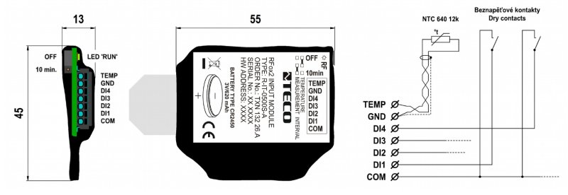
| Product dimensions (width x height x depth) | 45 × 55 × 13 mm |
| Operating conditions, product standards | |
| Product standard | ČSN EN 60730-1 ed.4 :2017 (EN 60730-1:2016) -Automatic electronic control device (for household and similar purposes) |
| Protection class of electrical object | III, according to ČSN EN 61140 ed.3: 2016 (idt IEC 61140:2016) |
| IP rating (Ingress Protection) according to ČSN EN 60529: 1993 (idt IEC 529: 1989) | IP20 |
| Operating areas | Normal, acc. ČSN 33 2000-1 ed.2: 2009 (mod IEC 60354-1:2005) |
| Degree of pollution | 2, according to ČSN EN 60664-1 ed.2: 2008 (idt IEC 60664-1: 2007) |
| Overvoltage category installation | II, according to EN 60664-1 ed_2: 2008 (idt IEC 60641-1: 2007) |
| Type of device | In the installation box, under the cover |
| Working position | Vertical |
| Type of operation (operating frequency) | Continuous |
| Ambient operating temperatures | -20 °C to + 55 °C |
| Operating relative humidity | from 10 % up to 95 % without condensation |
| Operating atmospheric pressure | min. 70 kPa (<3,000 m above sea level) |
| Storage temperatures | –25 °C to +70 °C |
| Electromagnetic compatibility, Mechanical endurance | |
| Electromagnetic compatibility / Emission | B, according to EN 55032 ed. 2: 2017 (idt CISPR 32: 2015) |
| Electromagnetic compatibility / Immunity | min. according to ČSN EN 60730-1 ed.3: 2012 |
| Sinusoidal vibration endurance | 10 Hz to 57 Hz, amplitude 0,075 mm, 57 Hz to 150 Hz, acceleration 1 G (Fc test according to EN 60068-2-6: 1997 (idt IEC 68-2-6: 1995), 10 cycles per axis.) |
| Packaginng, transportation, storage | |
| Description | The module is packed in an antistatic bag. The documentation includes documentation. The outer packaging shall be carried out according to the scope of the order and the mode of transport in a transport package provided with a label and other data necessary for transport. The product must not be exposed to direct weathering during transport and storage. Storage of the product is allowed only in clean rooms without conductive dust, aggressive gases and apparatus. The most suitable storage temperature is 20 ° C |
| Connection | |
| Connection description |
The module is mounted by suitable attachment, eg with a cable tie or it can be placed in the installation box. The connection of the module is realized by the terminal block with sperm terminals. These are intended for the connection of a rigid conductor. If it is necessary to connect a stranded wire, it is necessary to crimp a suitable cable gland at its end. Wire connection or The output of the temperature sensor is done by inserting it into the oval hole of the terminal. The wire is released by pushing the tip of a flat-blade screwdriver (size 0.4mm × 2mm) into the rectangular hole above the wire hole. The dimensions of the module and its usual connection are shown in the following figure |
| Connection of inputs / outputs | terminal block with spring clamp 0.15-0.5 mm2, push-in |
| Module operation | |
| Commissioning |
The module is equipped with a jumper for activating / deactivating the periodic transmission of the measured temperature value. Periodic transmission is deactivated by the manufacturer. The position of the jumper must be changed before connecting the battery. After connecting the battery supply voltage (by removing the insulating foil under the battery), the module is ready for operation. It does not contain any controls and is operated and diagnosed from the MOSAIC programming environment. The HW address is indicated on the label on the front panel The module must be operated by a person with the prescribed qualification for such an activity and this person must be thoroughly acquainted with the principles of working with the module. If the module is connected to parts that are under dangerous voltage, all necessary measures must be taken to protect users and equipment from electric shock. Workers installing and / or maintaining the equipment must be equipped and use personal protective equipment and other safety equipment at work. If the module is used in a manner not specified by the manufacturer, the protection provided by the module may be reduced. |
| Module diagnostics | Basic diagnostics are performed internally and the results are available in the appropriate Mosaic environment registries. The transmission of the module is indicated by a green RF LED. |
| Maintenance | |
| Instructions | The module does not require any maintenance if the general conditions for installation are observed. Operations that require the module to be assembled or disassembled are always performed with the battery disconnected. |
| Warning | Because the module contains semiconductor components, it is necessary to follow the principles for working with components sensitive to electrostatic charges during handling. It is not allowed to directly touch the printed circuit boards without protective measures. |
| Warranty | |
| Generally | Warranty and complaint conditions are governed by the Terms and Conditions of Teco a.s. |
| Notice | You must meet all the conditions of this documentation before turning on the system. The system must not be put into service unless it has been verified and confirmed that the machinery meets the requirements of Directive 89/392 / EEC, in so far as it applies to it. Documentation subject to change. |
HW documentation
R-IT-0500S-A - Basic documentation
303.61 kB
Files for designers
Foxtrot 2 - library of elements in DXF and DWG formats, v. 2025/08.
21.80 MB
Foxtrot 2 - element library for SchemataCAD, v. 2025/08.
6.96 MB
No data available.
No data available.