


C-RM-1109MTXN 133 82
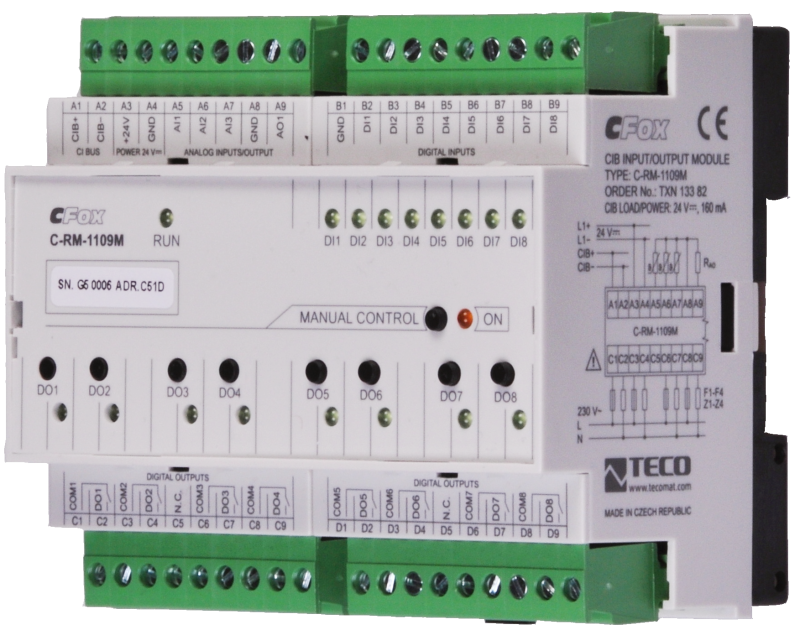
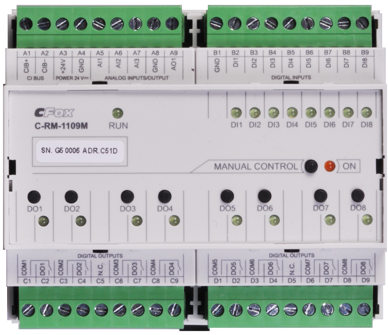
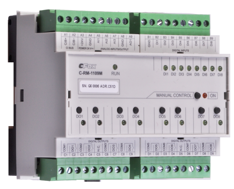
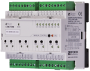
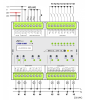
C-RM-1109M; CIB, 3x AI, 8X DI, 1x AO, 8x RO, ext. power supply
| DI | 8x DI |
|---|---|
| DI/AI | |
| DO | 8x RO |
| AI | 3x AI |
| AO | 1x AO |
| COM | 1x CIB slave |
| SENSOR |
| Picture | Variant | Variant description |
|---|---|---|

|
C-RM-1109M |
C-RM-1109M; CIB, 3x AI, 8X DI, 1x AO, 8x RO, ext. power supply
| Order num. | TXN 133 82 |
|---|---|
| Teco code | TXN 133 82 |
| Categories | CFox - Modules on DIN rail |
| Tags | - |
| COM - System buses | |
|---|---|
| CIB - Common Installation Bus (R): Installation I/O bus | 1x CIB slave |
| DI - Parameters of binary inputs DC (group A) | |
| Number of inputs in group | 8 |
| Common wire | GND - module ground |
| Input type | active (for dry contacts connection) |
| Galvanic isolation of inputs from internal/peripheral circuits | No |
| Diagnostics | signaling of the excited LED input on the module panel and in the Mosiac programming environment |
| The minimum width of the captured pulse | 5 ms |
| Max. contact current | 1,5 mA |
| Max. resistance for closed contact, log. 1 | < 1 kΩ |
| Min. resistance for open contact, log. 0 | > 2 kΩ |
| DO/RO - Organization of binary outputs | |
| Total number of binary outputs | 8 |
| RO - Parameters of binary relay outputs (group A) | |
| Parameters valid for the terminals | DO1, DO3, DO5, DO7 |
| Number of relay outputs | 4 |
| Number of output groups | 4 |
| Number of outputs in group | 1 |
| Organization of relay outputs into groups | 1+1+1+1 |
| Output type | electromechanical relay, unprotected output |
| Contact type | NO - Normally Open |
| Diagnose | Alarm signaling on panel module |
| Switching current | 16 A max., 100 mA min. |
| Switching voltage | 400 V AC max., 300 V DC max. |
| Switching power | 4000 VA max., 384 W max. |
| Short-term output overload - inrush | max. 800 A (max. 200 μs) |
| Contact closing time | typ. 15 ms |
| Contact opening time | typ. 5ms |
| Switching frequency with rated load | max. 20 switching / min. |
| Mechanical life | min. 5,000,000 cycles |
| Electrical life at maximum resistive load | min. 100,000 cycles |
| Short-circuit protection | No |
| Treatment of inductive load | External RC element, varistor (AC), diode (DC) |
| Insulation voltage between outputs and internal circuits | 4000 V AC |
| Isolation voltage between groups of outputs to each other | 4000 V AC |
| Insulation voltage between contacts | 1000 V AC |
| RO - Parameters of binary relay outputs (group B) | |
| Parameters valid for the terminals | DO2, DO4, DO6, DO8 |
| Number of relay outputs | 4 |
| Number of outputs in group | 1 |
| Organization of relay outputs into groups | 1+1+1+1 |
| Output type | electromechanical relay, unprotected output |
| Contact type | NO - Normally Open |
| Diagnose | Alarm signaling on panel module |
| Switching current | 10 A max., 100 mA min. |
| Switching voltage | max. 250 V AC; max. 30 V DC; min. 5 V |
| Switching power | 2500 VA max.; 300 W max. |
| Short-circuit protection | No |
| Contact closing time | typ. 10 ms |
| Switching frequency with rated load | max. 20 switching / min. |
| Mechanical life | min. 5,000,000 cycles |
| Treatment of inductive load | External RC element, varistor (AC), diode (DC) |
| Insulation voltage between outputs and internal circuits | 4000 V AC |
| Isolation voltage between groups of outputs to each other | 4000 V AC |
| Insulation voltage between contacts | 1250 V AC |
| AI - Organization of analog inputs | |
| Number of inputs per group | 3 |
| Number of analog input groups | 1 |
| Common wire | GND terminal |
| Galvanic separation from internal circuits | No |
| Digital resolution | 12 bit |
| AI - Analog Input Ranges (Group A) | |
| Voltage | 0-2 V |
| Passive sensor | Pt1000, W100 = 1,385 (-90 to +320 °C) |
| Passive sensor | Pt1000, W100 = 1,391 (-90 to +320 °C) |
| Passive sensor | Ni1000, W100 = 1,500 (–60 to +200 ° C) |
| Passive sensor | Ni1000, W100 = 1.617 (-60 to +200 ° C) |
| Passive sensor | Resistance transmitter 0-1 kOhm |
| Passive sensor | Resistance transmitter 0-100 kOhm |
| Passive sensor | KTY81-121; PTC thermistor (-55 to + 125 °C) |
| Passive sensor | NTC Thermistor 12k / 25 °C (-40 to + 125 °C) |
| AO - Analog output parameters | |
| Number of outputs in group | 1 |
| Galvanic isolation from internal circuits | No |
| Output type | active voltage output |
| Converter resolution | 8 bit |
| conversion time | 10 μs |
| Analog output error - maximum error at 25 ° C | ± 2% of full scale |
| Analog output error - temperature coefficient | ± 0.3% of full scale / K |
| Analog output error - linearity | ± 0.7% of full scale |
| Analog output error - repeatability under steady state conditions | ± 0.5% of full scale |
| Voltage output - voltage | 0 - 10,5 V |
| Voltage output - Resolution 1 LSB | 41 mV |
| Voltage output - maximum output current | 10 mA |
| Power supply | |
| Supply voltage, tolerances | 24 V DC ± 15% external power supply |
| Power supply from CIB - voltage | 24/27 V DC |
| Maximum power input | 4 W |
| Module thermal/power loss | 4 W |
| Power supply from CIB - maximum current consumption (mA) | 160 mA |
| Galvanic separation of power supply from internal circuits | No |
| Power supply from CIB - internal protection | No |
| Size and weight | |
| Weight approx. | 300 g |
| Product dimensions (width x height x depth) | 105 x 92 x 58 mm |
| Operating conditions, product standards | |
| Product standard | ČSN EN 60730-1 ed. 3:2012 (mod IEC 60730-1:2010) |
| Protection class of electrical object | I, according to ČSN EN 61140 ed.3: 2016 (idt IEC 61140:2016) |
| IP rating (Ingress Protection) according to ČSN EN 60529: 1993 (idt IEC 529: 1989) | IP10B |
| Operating areas | Normal, acc. ČSN 33 2000-1 ed.2: 2009 (mod IEC 60354-1:2005) |
| Degree of pollution | 1, according to ČSN EN 60664-1 ed.2:2008 ( idt IEC 60664-1:2007) |
| Overvoltage category installation | II, according to EN 60664-1 ed_2: 2008 (idt IEC 60641-1: 2007) |
| Type of device | Module on DIN rail |
| Working position | Vertical |
| Ambient operating temperatures | -10 °C to + 55 °C |
| Operating relative humidity | from 10 % up to 95 % without condensation |
| Operating atmospheric pressure | min. 70 kPa (<3,000 m above sea level) |
| Storage temperatures | –25 °C to +70 °C |
| Electromagnetic compatibility, Mechanical endurance | |
| Electromagnetic compatibility / Emission | B, according to EN 55032 ed. 2: 2017 (idt CISPR 32: 2015) |
| Electromagnetic compatibility / Immunity | min. according to ČSN EN 60730-1 ed.2: 2001 |
| Sinusoidal vibration endurance | 10 Hz to 57 Hz, amplitude 0,075 mm, 57 Hz to 150 Hz, acceleration 1 G (Fc test according to EN 60068-2-6: 1997 (idt IEC 68-2-6: 1995), 10 cycles per axis.) |
| Packaginng, transportation, storage | |
| Description | The module is packed in a paper box. This documentation is also part of the package. The outer packaging is carried out according to the scope of the order and the method of transport in a transport package provided with labels and other data necessary for transport. The product must not be exposed to direct weather conditions during transport and storage. Malting of the product is only allowed in clean rooms without conductive dust, aggressive gases and vapors. The most suitable storage temperature is 20 ° C |
| Installation | |
| Assembly description | The module is mounted in a vertical position on the U-rail ČSN EN 50022. Installation of the assembly (basic module and possibly peripheral modules) is performed according to TXV 004 13. |
| Connection | |
| Connection of power and system communication | connector with 2.5 mm2 screw terminal |
| Connection of inputs / outputs | connector with screw terminal 2.5 mm2 |
| Module installation tools | (-) 3 mm, flat screwdriver |
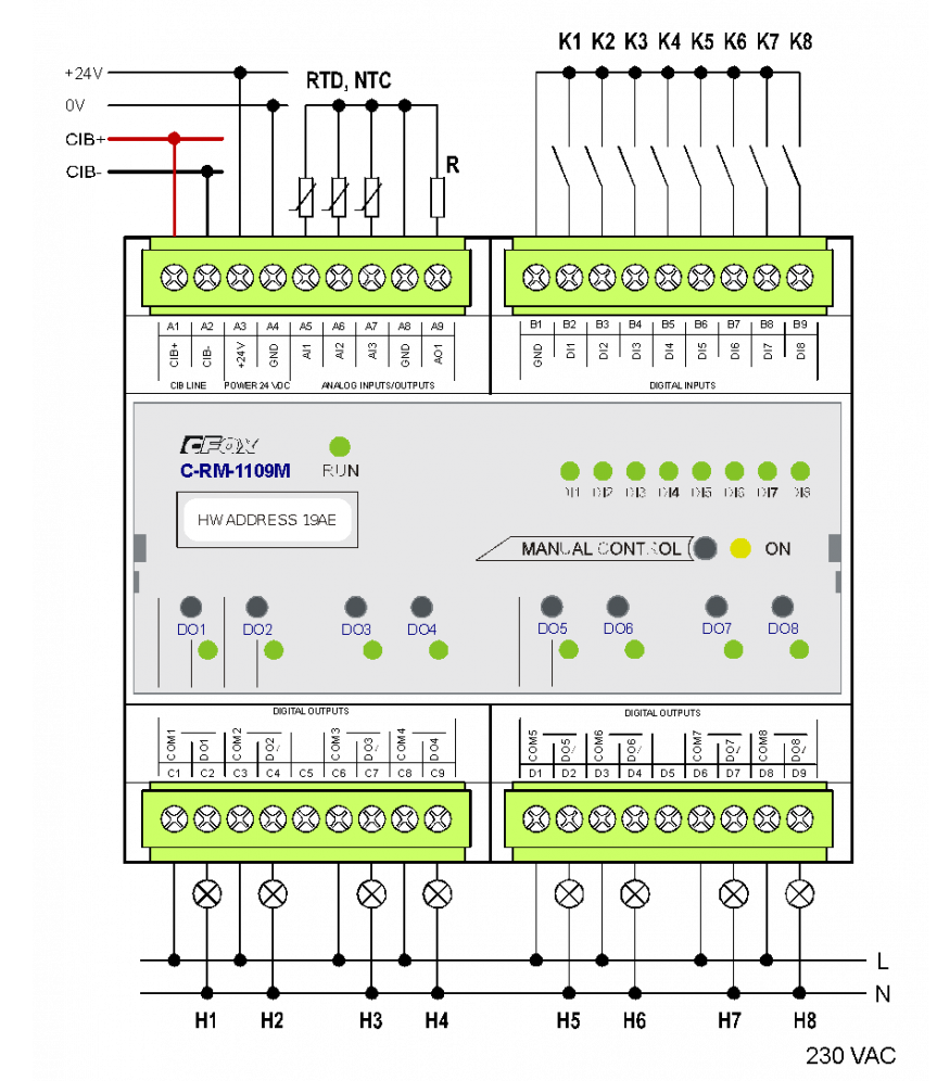
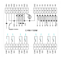
| Module connection | Module is designated for the connection to CIB that ensures communication. The module is supplied either from CIB or from the separate power supply 24 V DC. CIB bus has a free topology and branches up to 500 m and up to 32 units per one branch in case of supplying from the separate power supply. In case of supplying from the CIB the number of connected modules decreases to 6. As a CIB master, Foxtrot basic module or external CIB master CF-1141 can be used. The detailed information is stated in the manual Peripheral modules for CIB bus (No. TXV 004 13) The example of module connection is shown in the following picture. |
| Module operation | |
| Commissioning | The module is operated, set and diagnosed from the MOSAIC programming environment or other parameterization software. The module is ready for operation after connecting the supply voltage and the CIB bus. The HW address is indicated on the label on the module. |
| Module diagnostics | The basic diagnostics is performed internally and the result is available in the relevant registers of the Mosaic environment. |
| Maintenance | |
| Description | The module does not require any maintenance under general installation conditions. The operations in which a part of the module has to be dismantled must always be carried out with the supply voltage disconnected. |
| Notice | Because the module contains semiconductor components, it is necessary to follow the principles for working with electrostatic sensitive components when handling the removed cover. It is not allowed to directly touch the printed circuit boards without protective measures !!! |
| Warranty | |
| Generally | Warranty and complaint conditions are governed by the Terms and Conditions of Teco a.s. |
| Notice | You must meet all the conditions of this documentation before turning on the system. The system must not be put into service unless it has been verified and confirmed that the machinery meets the requirements of Directive 89/392 / EEC, in so far as it applies to it. Documentation subject to change. |
HW documentation
C-RM-1109M - Basic documentation
1.54 MB, (EN)
User manuals
Peripheral module on CIB-Common Installation Bus(R) (cs), TXV00413_01
14.01 MB
Peripheral modules on the CIB Common Installation Bus(R) (en), TXV00413_02
13.94 MB, (EN, RU, DE, UA)
Files for designers
Foxtrot 2 - library of elements in DXF and DWG formats, v. 2025/08.
21.80 MB
Foxtrot 2 - element library for SchemataCAD, v. 2025/08.
6.96 MB
EC - Declaration of Conformity
Foxtrot - EC Declaration of conformity
295.20 kB, (EN, RU, DE, UA)
- C-RM-1109M - ...Maximum load capacity 50 nF Fig. 1. An example of connecting the C-RM-1109M module. Notes: The GND and CIB- terminals are interconnected, see the interna...
- Power dissipation of modules for calculation of switchboard heating - ...put, connection of cell sensors and 2x relays) C-BM-0202M 1,5 W TXN 133 82 C-RM-1109M; CIB, 3x AI, 8X DI, 1x AO, 8x RO, ext. power supply C-RM-1109M 4,0 W TXN...
No data available.