


C-IT-0504LTXN 143 26
C-IT-0504L; CIB, 5x AI/DI RTD or contact, 4x AO (0-10V/10mA)
| DI | |
|---|---|
| DI/AI | 5x DI/AI |
| DO | |
| AI | |
| AO | 4x AO |
| COM | 1x CIB slave |
| SENSOR |
| Picture | Variant | Variant description |
|---|---|---|

|
C-IT-0504L |
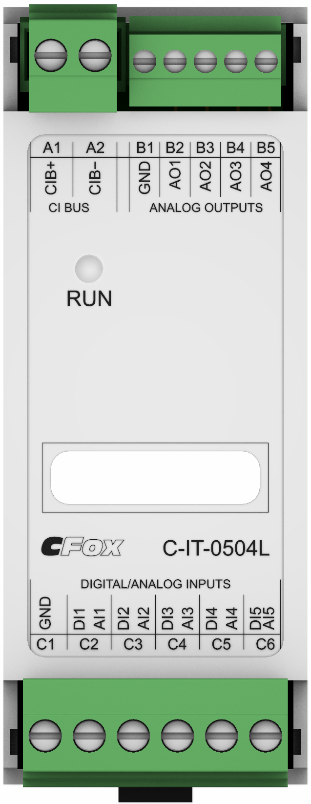
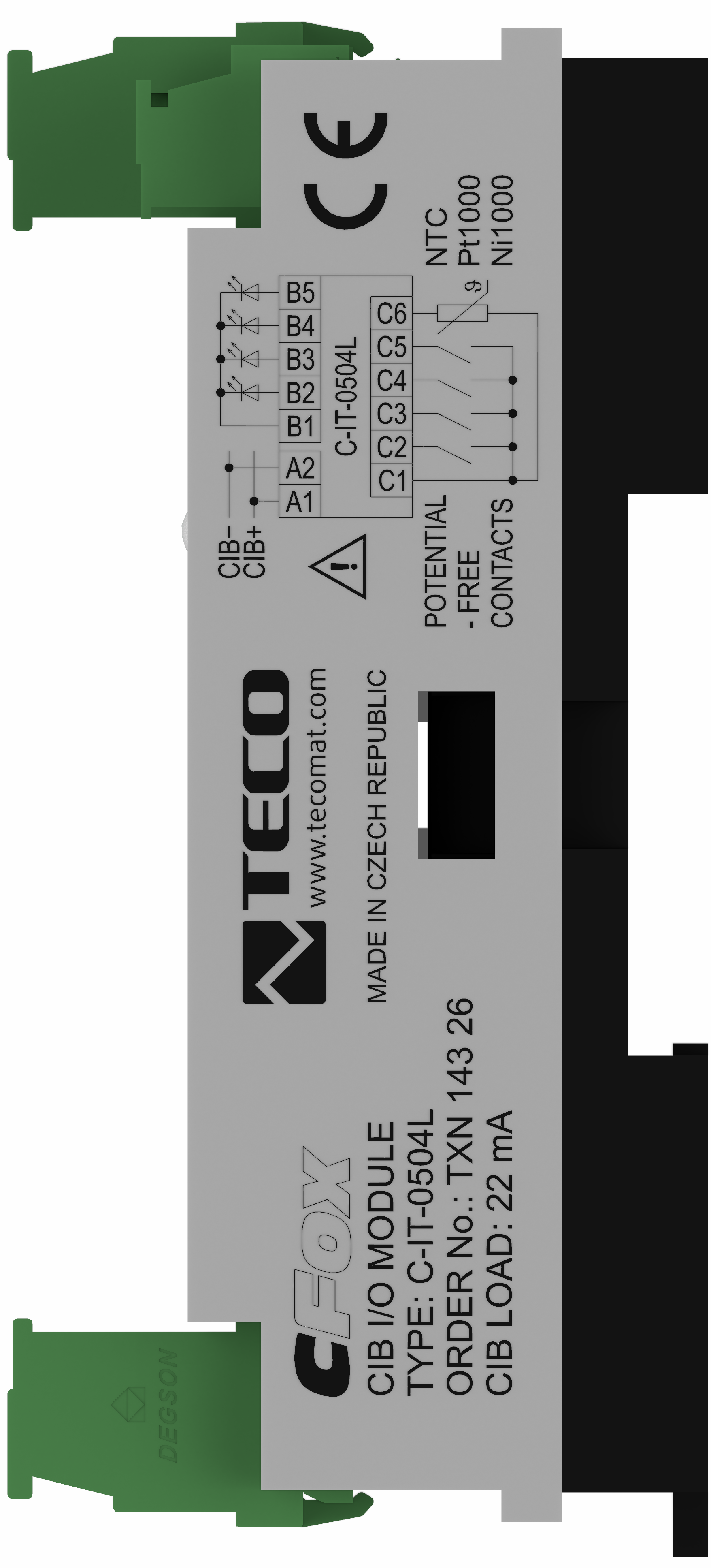
The C-IT-0504L module (order no.: TXN 143 26) is designed for connecting analog or binary signals and analog outputs 0 - 10 V directly to the CIB wiring bus. Inputs, outputs and buses are connected to the module via connectors. Universal inputs can be set to binary or analog by program in two groups. The first group contains 4 inputs, the second 1 input. The setting is then common for the entire group.
For example, one temperature sensor and four input-contacts or one input-contact and four temperature sensors. Resistance sensors PT1000 or Ni1000 or a sensor with a thermistor NTC12k or KTY81-121 against a common GND conductor are used for temperature measurement. The resistance is converted in the module to a numerical temperature value and transmitted to the central unit via the CIB bus. For another type of resistance sensor, a resistance measurement range of 0 to 160 kΩ can be selected, but the conversion to temperature and linearization must be performed only at the level of the user program. The module software - firmware - is optimized to increase the accuracy and linearize the measuring range of the sensor in the module.
Binary signals are connected to the inputs only as free, without voltage contact against the common conductor GND. The binary input can also operate in balanced input mode. The voltage of the analog outputs 0 - 10 V is output on the conductor against the common GND conductor.
| Order num. | TXN 143 26 |
|---|---|
| Teco code | TXN 143 26 |
| Categories | CFox - Modules on DIN rail |
| Tags | New |
| COM - System buses | |
|---|---|
| CIB - Common Installation Bus (R): Installation I/O bus | 1x CIB slave |
| DI - Organization of binary inputs | |
| Total number of binary inputs | 5 |
| Number of groups of binary inputs | 2 |
| Organization of binary inputs into groups |
4x DI (DI/AI1 - DI/AI4) 1x DI (DI/AI5) |
| DI - Parameters of binary inputs DC | |
| Parameters valid for inputs on the terminals | DI/AI1 - DI/AI5 |
| Common wire | GND - module ground |
| Combined input type | DI/AI Active, for sensing potential-free contacts and measuring resistance sensors |
| Galvanic isolation of inputs from internal/peripheral circuits | No |
| Galvanic separation of inputs from CIB bus | No |
| Internal input resistance | 2 kΩ |
| Max. resistance for closed contact, log. 1 | < 0,5 kΩ |
| Min. resistance for open contact, log. 0 | ≥ 2,7 kΩ |
| Balanced resistance input | 2× 1k1 (tamper/0/1/tamper) |
| AI - Organization of analog inputs | |
| Total number of analog inputs | 5 |
| Number of analog input groups | 2 |
| Organization of analog inputs into groups |
4x DI (DI/AI1 - DI/AI4) 1x DI (DI/AI5) |
| Input type |
4x DI (DI/AI1 - DI/AI4) 1x DI (DI/AI5) |
| Common wire | GND terminal |
| Galvanic separation from internal circuits | No |
| Galvanic isolation of the inputs from each other | No |
| AI - Analog Input Ranges | |
| Passive sensor | Pt1000, W100 = 1,385 (-90 to +320 °C) |
| Passive sensor | Pt1000, W100 = 1,391 (-90 to +320 °C) |
| Passive sensor | Ni1000, W100 = 1,500 (–60 to +200 °C) |
| Passive sensor | Ni1000, W100 = 1.617 (-60 to +200 °C) |
| Passive sensor | Resistance transmitter 0-160 kOhm |
| Passive sensor | KTY81-121; (-55 to + 125 °C) |
| Passive sensor | NTC Thermistor 12k / 25 °C (-40 to + 125 °C) |
| Input impedance in signal range RTD | 2,0 kΩ |
| Resistance measurement error - maximum error at 25 ° C | ±0.5% of full scale, ±2% of value |
| AO - Analog output parameters | |
| The number of groups of analogue outputs | 1 |
| Number of outputs in group | 4 |
| Number of outputs and their organization into groups | 4x AO (AO1-AO4) |
| Common wire of group | GND terminal |
| Galvanic isolation from internal circuits | No |
| Output type | active voltage output |
| Voltage output - voltage | 0 - 10 V |
| Voltage output - Resolution 1 LSB | 10,546 mV |
| Voltage output - Adjustable range | 0 ÷ 125 % Ujm |
| Voltage output - Load resistance | >1 kΩ |
| Voltage output - Load capacity | 250 nF |
| Voltage output - maximum output current | 10 mA |
| Voltage output - Maximum output current for the group | 15 mA |
| Power supply | |
| Supply voltage, tolerances | 24/27 V DC from CIB bus |
| Power supply from CIB - maximum current consumption (mA) | 42 mA |
| Size and weight | |
| Weight approx. | 60 g |
| Product dimensions (width x height x depth) | 35 × 92 × 42 mm |
| Operating conditions, product standards | |
| Product standard | ČSN EN 60730-1 ed.4 :2017 (EN 60730-1:2016) -Automatic electronic control device (for household and similar purposes) |
| Protection class of electrical object | III, according to ČSN EN 61140 ed.3: 2016 (idt IEC 61140:2016) |
| IP rating (Ingress Protection) according to ČSN EN 60529: 1993 (idt IEC 529: 1989) | IP20 |
| Operating areas | Normal, acc. ČSN 33 2000-1 ed.2: 2009 (mod IEC 60354-1:2005) |
| Degree of pollution | 1, according to ČSN EN 60664-1 ed.2:2008 ( idt IEC 60664-1:2007) |
| Overvoltage category installation | II, according to EN 60664-1 ed_2: 2008 (idt IEC 60641-1: 2007) |
| Type of device | Module on DIN rail |
| Working position | Any |
| Type of operation (operating frequency) | Continuous |
| Ambient operating temperatures | 0 ° C to + 70 ° C |
| Operating relative humidity | from 10 % up to 95 % without condensation |
| Operating atmospheric pressure | min. 70 kPa (<3,000 m above sea level) |
| Storage temperatures | –25 ° C to + 85 ° C |
| Electromagnetic compatibility, Mechanical endurance | |
| Electromagnetic compatibility / Emission | ČSN EN 55022 ed2:2007 (mod CISPR22:2005) |
| Electromagnetic compatibility / Immunity | min. according to ČSN EN 60730-1 ed.2: 2001 |
| Sinusoidal vibration endurance | 10 Hz to 57 Hz, amplitude 0,075 mm, 57 Hz to 150 Hz, acceleration 1 G (Fc test according to EN 60068-2-6: 1997 (idt IEC 68-2-6: 1995), 10 cycles per axis.) |
| Packaginng, transportation, storage | |
| Description | Модуль упакован в антистатический пакет. Эта документация также является частью пакета. Внешняя упаковка осуществляется в соответствии с объемом заказа и способом транспортировки в транспортной упаковке, снабженной этикетками и другими данными, необходимыми для транспортировки. Продукт не должен подвергаться воздействию прямых погодных условий во время транспортировки и хранения. Соложение продукта разрешено только в чистых помещениях. без токопроводящей пыли, агрессивных газов и паров. Наиболее подходящая температура хранения - 20 ° C. |
| Connection | |
| Connection of power and system communication | connector with 2.5 mm2 screw terminal |
| Connecting inputs | connector with screw terminal 2.5 mm2 |
| Connecting outputs | connector with screw terminal 1.5 mm2 |
| Module operation | |
| Module configuration | The module is operated, set up and diagnosed from the Mosaic development environment. |
| Commissioning | The module is operated, set and diagnosed from the MOSAIC programming environment or other parameterization software. The module is ready for operation after connecting the supply voltage and the CIB bus. The HW address is indicated on the label on the module. |
| Module diagnostics | The basic diagnostics is performed internally and the result is available in the relevant registers of the Mosaic environment. |
| Maintenance | |
| Description | The module does not require any maintenance under general installation conditions. The operations in which a part of the module has to be dismantled must always be carried out with the supply voltage disconnected. |
| Notice | Because the module contains semiconductor components, it is necessary to follow the principles for working with electrostatic sensitive components when handling the removed cover. It is not allowed to directly touch the printed circuit boards without protective measures !!! |
| Warranty | |
| Generally | Warranty and complaint conditions are governed by the Terms and Conditions of Teco a.s. |
| Notice | You must meet all the conditions of this documentation before turning on the system. The system must not be put into service unless it has been verified and confirmed that the machinery meets the requirements of Directive 89/392 / EEC, in so far as it applies to it. Documentation subject to change. |
User manuals
Peripheral module on CIB-Common Installation Bus(R) (cs), TXV00413_01
14.01 MB
Peripheral modules on the CIB Common Installation Bus(R) (en), TXV00413_02
13.94 MB, (EN, RU, DE, UA)
HW documentation
C-IT-0504L - Basic documentation
2.99 MB, (EN)
EC - Declaration of Conformity
Foxtrot 2 - EC Declaration of conformity (en)
590.59 kB, (EN, RU, DE, UA)
Files for designers
Foxtrot 2 - library of elements in DXF and DWG formats, v. 2025/08.
21.80 MB
Foxtrot 2 - element library for SchemataCAD, v. 2025/08.
6.96 MB
- C-IT-0504L, CIB Analog module - ...ile DIN rail enclosure ( 2M wide ) with a connector featuring screw terminals . The C-IT-0504L module (order no.: TXN 143 26) is designed for connecting analog or binary signals and 0–10 V analog outputs...
No data available.