


C-IR-0203MTXN 133 59
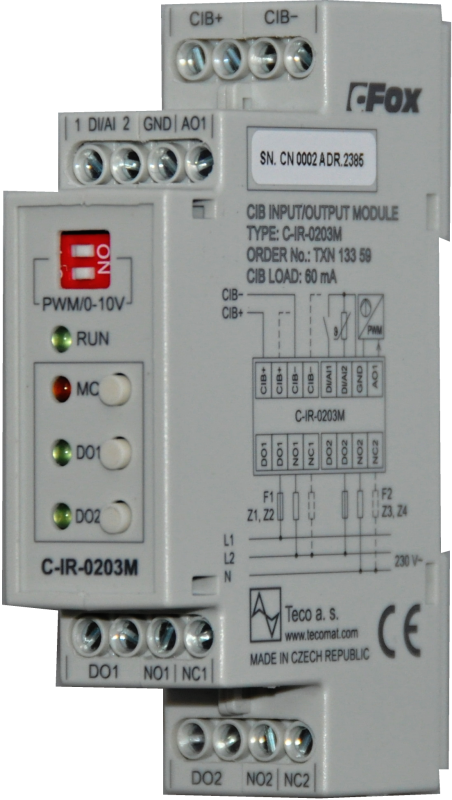
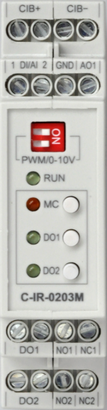
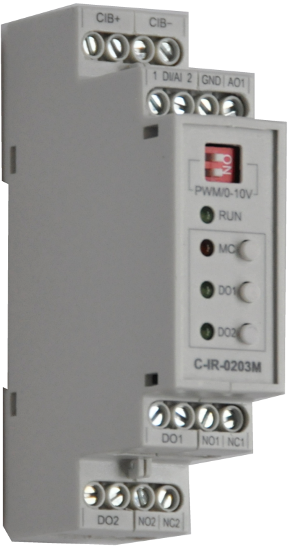
C-IR-0203M; CIB, 2x DI / AI, 2x RO switching contacts 230V / 16A, 1x AO 0-10V / PWM
| DI | |
|---|---|
| DI/AI | 2x DI/AI |
| DO | 2x RO (NO/NC 16/10A) |
| AI | |
| AO | 1x AO/PWM |
| COM | 1x CIB slave |
| SENSOR |
| Picture | Variant | Variant description |
|---|---|---|

|
C-IR-0203M |
C-IR-0203M is a module on the CIB bus with a total of 5 inputs / outputs in combination:
- 2 AI / DI inputs
- 2 relay outputs with changeover contact (each contact shown separately on the terminal board)
- 1 AO output with a range of 0 to 10V, or with a PWM output with adjustable amplitude and frequency.
- Closed loop control with proportional control (PWM output) or two-point control (relay)
- Control of valves, motors, lighting switching, heating cartridges and other general loads and appliances
- Simple measurement of two quantities by passive / resistance sensors
| Order num. | TXN 133 59 |
|---|---|
| Teco code | TXN 133 59 |
| Categories | CFox - Modules on DIN rail |
| Tags | - |
| COM - System buses | |
|---|---|
| CIB - Common Installation Bus (R): Installation I/O bus | 1x CIB slave |
| RO - Parameters of binary relay outputs (group A) | |
| Number of relay outputs | 2 |
| Number of output groups | 2 |
| Number of outputs in group | 1 |
| Output type | electromechanical relay, unprotected output |
| Contact type | NO / NC changeover contact |
| Diagnose | Alarm signaling on panel module |
| Switching current | 16 A max., 100 mA min. |
| Switching voltage | 250 V AC max., 5 V AC min., 30V DC max. |
| Short-term output overload - inrush | 80 A max. (20 ms max.) |
| Contact closing time | typ. 15 ms |
| Contact opening time | typ. 5ms |
| Mechanical life | min. 20 000 000 cycles |
| Short-circuit protection | No |
| Insulation voltage between outputs and internal circuits | 3750 V AC |
| Isolation voltage between groups of outputs to each other | 3750 V AC |
| AI - Organization of analog inputs | |
| Total number of analog inputs | 2 |
| Number of inputs per group | 2 |
| Number of analog input groups | 1 |
| Input type | With common clamp |
| Common wire | Minus |
| Galvanic separation from internal circuits | No |
| Diagnostics | overload signaling in status word |
| External power supply | No |
| Digital resolution | 12 bit |
| Converter type | Approximation |
| Analog input error - Temperature coefficient | ± 0,03% of full scale |
| Analog input error - Nonlinearity | ± 0.07% of full scale |
| Analog input error - Steady state repeatability | 0.05% of full scale |
| AI - Analog Input Ranges (Group A) | |
| Passive sensor | Pt1000, W100 = 1,385 (-90 to +320 °C) |
| Passive sensor | Pt1000, W100 = 1,391 (-90 to +320 °C) |
| Passive sensor | Ni1000, W100 = 1,500 (–60 to +200 ° C) |
| Passive sensor | Ni1000, W100 = 1.617 (-60 to +200 ° C) |
| Passive sensor | KTY81-121; PTC thermistor (-55 to + 125 °C) |
| DI: Voltage-free contact | 0 when> 1.5 kOhm, 1 when <0.5 kOhm |
| DI: Balanced resistance input | 2x 1k1 (tamper/0/1/tamper) |
| Resistance measurement error - maximum error at 25 ° C | ± 0.5% of full scale |
| Resistance measurement error - temperature coefficient | ± 0.05% of full scale / K |
| Resistance measurement error - non-linearity | ± 0.09% of full scale |
| AO - Analog output parameters | |
| Number of outputs in group | 1 |
| Common wire of group | AGND terminal |
| Galvanic isolation from internal circuits | No |
| Output type | active voltage output |
| Analog output error - maximum error at 25 ° C | ± 0.3% of full scale |
| Analog output error - temperature coefficient | ± 0.3% of full scale / K |
| Analog output error - linearity | ± 0.7% of full scale |
| Analog output error - repeatability under steady state conditions | ± 0.5% of full scale |
| Voltage output - maximum output current | 10 mA |
| Power supply | |
| Nominal supply voltage (V) | 24 V DC |
| Supply voltage, tolerances | 24/27 V DC from CIB bus |
| Typical power input | 1 W |
| Maximum power input | 2 W |
| Module thermal/power loss | 1,5 W |
| Power supply from CIB - maximum current consumption (mA) | 80 mA |
| Galvanic separation of power supply from internal circuits | No |
| Description of power supply | Difference between typical and maximum power input is given by possible load of CIB buses and number of switched outputs and CPU load |
| Size and weight | |
| Weight approx. | 100 g |
| Product dimensions (width x height x depth) | 18 x 90 x 58 mm |
| Module width in multiples of M (17.5 mm) | 1,5M |
| Module height | 90 mm |
| Module depth | 58 mm |
| Operating conditions, product standards | |
| Product standard | ČSN EN 61131-2:2008 (idt IEC 61131-2:2007) - Programmable control units |
| Protection class of electrical object | I, according to ČSN EN 61140 ed.3: 2016 (idt IEC 61140:2016) |
| IP rating (Ingress Protection) according to ČSN EN 60529: 1993 (idt IEC 529: 1989) | IP20 |
| Operating areas | Normal, according to ČSN 33 2000-3: 1995 (mod IEC 364-3: 1993) |
| Degree of pollution | 1, according to ČSN EN 60664-1 ed.2:2008 ( idt IEC 60664-1:2007) |
| Overvoltage category installation | I, according to ČSN EN 60664-1 ed_2:2008 (idt IEC 60641-1:2007) |
| Type of device | Module on DIN rail |
| Working position | Vertical |
| Type of operation (operating frequency) | Continuous |
| Ambient operating temperatures | -20 °C to + 55 °C |
| Operating temperature maximum (° C) | +55°C |
| Operating temperature minimum (° C) | -20°C |
| Operating relative humidity | from 10 % up to 95 % without condensation |
| Operating atmospheric pressure | min. 70 kPa (<3,000 m above sea level) |
| Storage temperatures | –25 °C to +70 °C |
| Electromagnetic compatibility, Mechanical endurance | |
| Electromagnetic compatibility / Emission | A, according to EN 55032 ed. 2: 2017 (idt CISPR 32: 2015) |
| Emmisions - note | In premises where the use of radio and television receivers can be expected to be used a distance of 10 m from these devices may cause radio interference. In such a case, the user may be required to take appropriate action. |
| Electromagnetic compatibility / Immunity | min. as required by EN 61131-2: 2007 |
| Sinusoidal vibration endurance | 10 Hz to 57 Hz, amplitude 0,075 mm, 57 Hz to 150 Hz, acceleration 1 G (Fc test according to EN 60068-2-6: 1997 (idt IEC 68-2-6: 1995), 10 cycles per axis.) |
| Packaginng, transportation, storage | |
| Description | The module is packed in a paper box. This documentation is also part of the package. The outer packaging is carried out according to the scope of the order and the method of transport in a transport package provided with labels and other data necessary for transport. The product must not be exposed to direct weather conditions during transport and storage. Malting of the product is only allowed in clean rooms without conductive dust, aggressive gases and vapors. The most suitable storage temperature is 20 ° C |
| Installation | |
| Assembly description | Switchboard mounting |
| Attention! | The device may contain parts with dangerous voltages, covers being removed, or cabling manipulated, or disconnect the appropriate circuits or turn off the power !. |
| Connection | |
| Connection of power and system communication | terminal block with screw terminal 2.5 mm2 |
| Connection of inputs / outputs | terminal block with screw terminal 2.5 mm2 |
| Module operation | |
| Module configuration | The module is operated, set up and diagnosed from the Mosaic development environment. |
| Maintenance | |
| Description | The module does not require any maintenance under general installation conditions. |
| Notice | Because the module contains semiconductor components, it is necessary to follow the principles for working with electrostatic sensitive components when handling the removed cover. It is not allowed to directly touch the printed circuit boards without protective measures !!! |
| Warranty | |
| Generally | Warranty and complaint conditions are governed by the Terms and Conditions of Teco a.s. |
| Notice | You must meet all the conditions of this documentation before turning on the system. The system must not be put into service unless it has been verified and confirmed that the machinery meets the requirements of Directive 89/392 / EEC, in so far as it applies to it. Documentation subject to change. |
HW documentation
C-IR-0203M - Basic documentation
792.93 kB, (EN)
User manuals
Peripheral module on CIB-Common Installation Bus(R) (cs), TXV00413_01
14.01 MB
Peripheral modules on the CIB Common Installation Bus(R) (en), TXV00413_02
13.94 MB, (EN, RU, DE, UA)
Files for designers
Foxtrot 2 - library of elements in DXF and DWG formats, v. 2025/08.
21.80 MB
Foxtrot 2 - element library for SchemataCAD, v. 2025/08.
6.96 MB
EC - Declaration of Conformity
Foxtrot 2 - EC Declaration of conformity (en)
590.59 kB, (EN, RU, DE, UA)
- C-IR-0203M - The C-IR-0203M is a module on the CIB bus, which comprises of two universal analogue or binary inputs, two relay outputs with a changeover contact (each is separately terminated) and one output optionally adjustable as analogue, with the range fr...
- Power dissipation of modules for calculation of switchboard heating - ...2x dimmer RLC, 230V AC, 2x 500W, 4x DI/AI C-DM-0402M-RLC 5,0 W TXN 133 59 C-IR-0203M; CIB, 2x DI/AI, 2x RO switching contacts 230V/16A, 1x AO 0-10V/PWM C-IR-0203M 1,5 W...
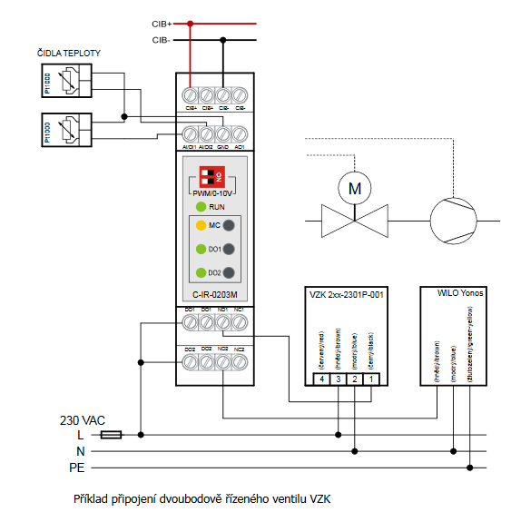
- Two-point controlled VZK zone ball valve - ...mple of electrical connection of the VZK 2xx - 230 - 1P – 001 zone valve produced by Regulus. It is controlled by the C-IR-0203M module together with the Wilo Yonos circulation pump . Fig. 1. An example of connecting a two...
- Measurement of radiant heat in halls (industrial heating) - ...es of connection of a number of peripheral modules, such as connecting the Pt1000 sensor to the AI1 and AI2 inputs of the C-IR-0203M module ....
- An example of dimming the CREE power LED chips by the C-DM-0006M-ILED module - ...network and needlessly consume current, its input is switched by a 230VAC relay output; in this case the DO1 input of the C-IR-0203M module is used. The inrush current (so-called “cold start”) of the power supply DR-60-12...
- Continuous power control el. TV heating, SSR module - ...s, eg for outputs up to approx. 3 kW module RGS1A23D25, controlled by PWM output of the system - in the example used module C-IR-0203M . The module allows you to switch 2 heating coils and control the third continuously with PWM output (thus obtaini...
No data available.