

C-IS-0504MTXN 133 49
C-IS-0504M; CIB, 3x AI/DI, 3x RO, 1x PWM (4W), 2x AI resistance measuring by AC)
| DI | |
|---|---|
| DI/AI | 3x DI/AI |
| DO | 1x RO 16A 2x RO 3A 1x DO (PWM) |
| AI | 2x AI (AC resistance measurement <1MΩ) |
| AO | |
| COM | 1x CIB slave |
| SENSOR |
| Picture | Variant | Variant description |
|---|---|---|

|
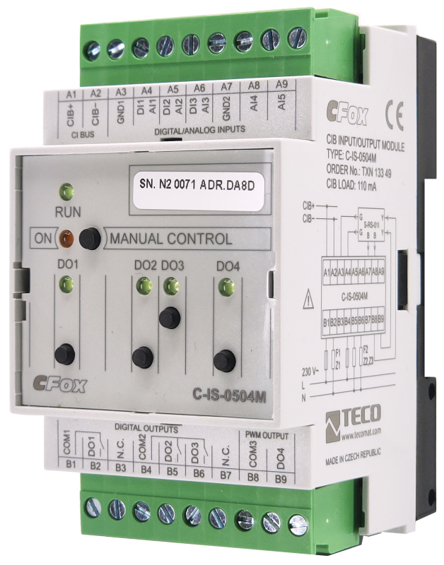
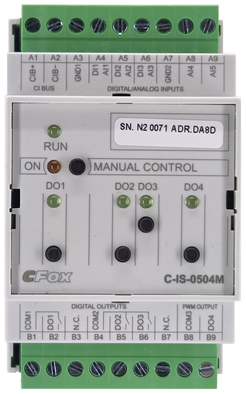
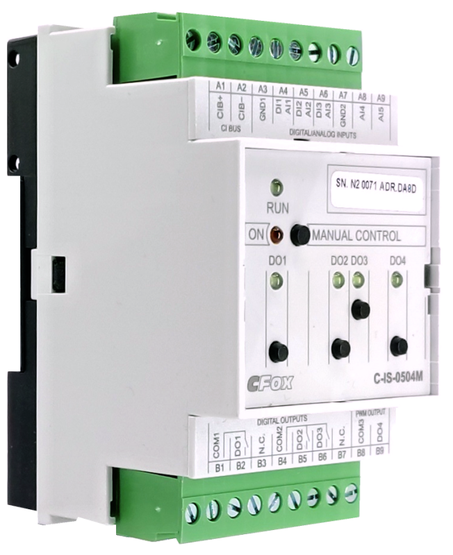
C-IS-0504M |
C-IS-0504M is a module on the CIB bus with a total of 9 inputs / outputs in combination
- 3x combined AI / DI input for sensing contacts and measuring resistance thermometers,
- 2x analog input specialized for measuring AC resistances
- (excluding long-term electrolysis in a humid environment - icing, precipitation, level probes)
- 1x semiconductor output with pulse width modulation (PWM from 100 Hz to 2 kHz and load capacity max. 4W)
- 2x relay output 5 A,
- 1x relay output 16A, with resistance to inrush current up to 80 A
- The individual relay outputs have a status LED indication and can be manually controlled locally by buttons on the module panel.
- Inputs and outputs can be used as general AI / DI and RO
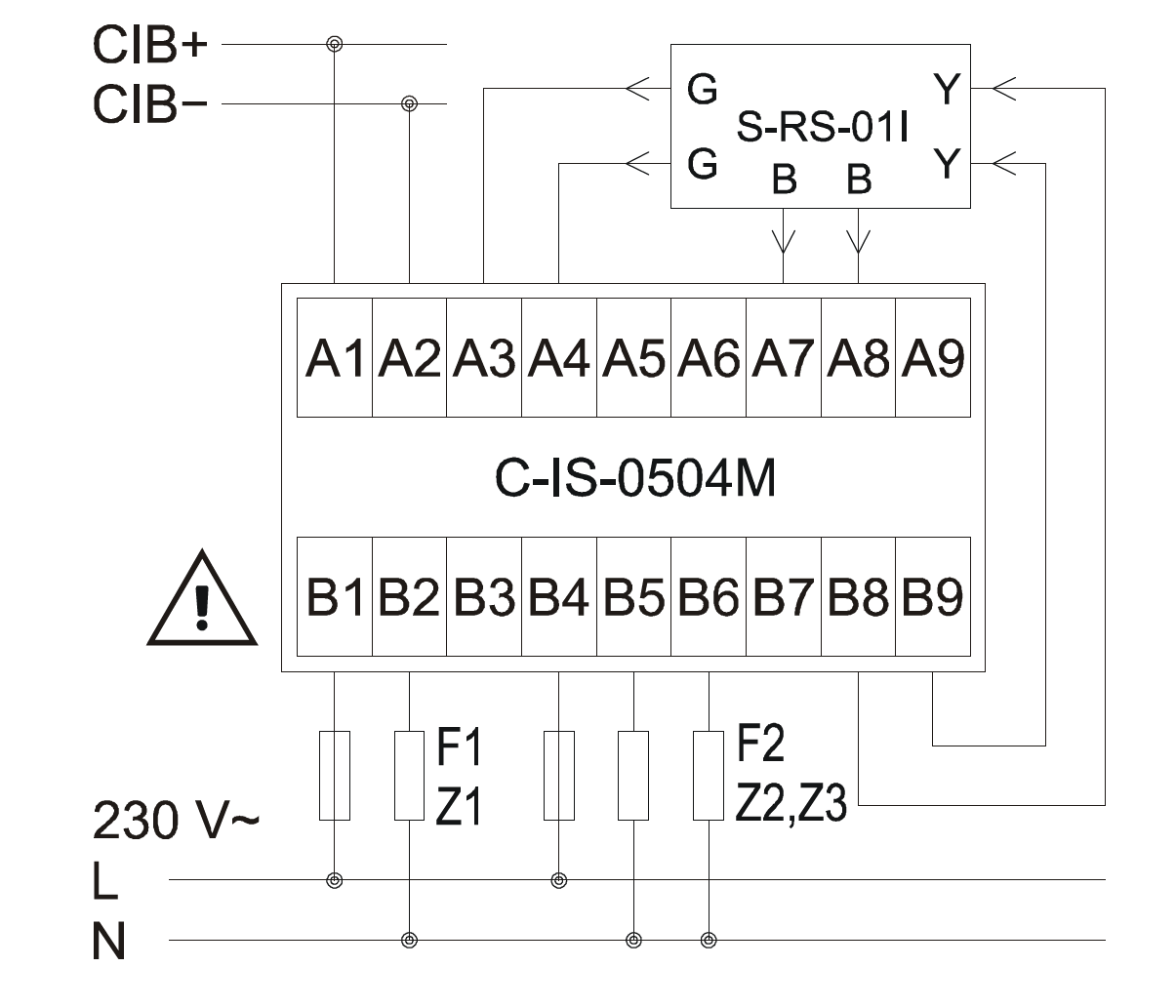
- Controlled heating supply and measurement of precipitation detector S-RS-01I,
- Heating supply and measurement of icing sensors with a nominal voltage of 24 V.
- Up to 2 probes for level measurement, eg for limit monitoring of water in the tank.
| Order num. | TXN 133 49 |
|---|---|
| Teco code | TXN 133 49 |
| Categories | CFox - Modules on DIN rail |
| Tags | - |
| COM - System buses | |
|---|---|
| CIB - Common Installation Bus (R): Installation I/O bus | 1x CIB slave |
| DO/RO - Organization of binary outputs | |
| Total number of binary outputs | 4 |
| Number of binary output groups | 3 |
| Organization of binary outputs into groups |
1x RO 16A 2x RO 3A 1x PWM 24V/83mA |
| DO - Parameters of binary transistor outputs (group A) | |
| Number of transistor outputs | 1 |
| Common group conductor | minus |
| Output type | Semiconductor |
| Galvanic separation from internal circuits | No |
| Resting output level | 24 V DC +-10% |
| Switching current, output load | 83 mA max. |
| Short circuit protection | No |
| Special functions (A) | PWM |
| Operating frequency | 100 Hz ÷ 2 kHz |
| RO - Parameters of binary relay outputs (group A) | |
| Parameters valid for the terminals | DO1 |
| Number of relay outputs | 1 |
| Output type | electromechanical relay, unprotected output |
| Contact type | NO - Normally Open |
| Diagnose | Alarm signaling on panel module |
| Switching current | 16 A max., 100 mA min. |
| Switching voltage | 400 V AC max., 300 V DC max. |
| Short-term output overload - inrush | 80 A max. (20 ms max.) |
| Contact closing time | typ. 15 ms |
| Contact opening time | typ. 5ms |
| Mechanical life | min. 20 000 000 cycles |
| Short-circuit protection | No |
| Treatment of inductive load | External RC element, varistor (AC), diode (DC) |
| Insulation voltage between outputs and internal circuits | 4000 V AC |
| Isolation voltage between groups of outputs to each other | 4000 V AC |
| RO - Parameters of binary relay outputs (group B) | |
| Parameters valid for the terminals | DO2, DO3 |
| Number of relay outputs | 2 |
| Output type | electromechanical relay, unprotected output |
| Contact type | NO - Normally Open |
| Diagnose | Alarm signaling on panel module |
| Switching current | 3 A max., 100 mA min. |
| Switching voltage | max. 250 V AC; max. 30 V DC; min. 5 V |
| Short-circuit protection | No |
| Short-term output overload | 5 A max. (20 ms max.) |
| Contact closing time | typ. 10 ms |
| Contact opening time | typ. 10 ms |
| Mechanical life | min. 5,000,000 cycles |
| Treatment of inductive load | External RC element, varistor (AC), diode (DC) |
| Insulation voltage between outputs and internal circuits | 4000 V AC |
| Isolation voltage between groups of outputs to each other | 4000 V AC |
| Insulation voltage between contacts | 750 V AC |
| AI - Organization of analog inputs | |
| Total number of analog inputs | 5 |
| Number of analog input groups | 2 |
| Organization of analog inputs into groups | 3 (AI/DI 1 - 3) + 2 (AI4, AI5) |
| Input type | With common clamp |
| Common wire | GND terminal |
| Galvanic separation from internal circuits | No |
| AI - Analog Input Ranges (Group A) | |
| Parameters valid for inputs on the terminals | AI/DI1-AI/DI3 |
| Voltage | 0 to 2 V / 805.9 μV |
| Passive sensor | Pt1000, W100 = 1,385 (-90 to +320 °C) |
| Passive sensor | Pt1000, W100 = 1,391 (-90 to +320 °C) |
| Passive sensor | Ni1000, W100 = 1,500 (–60 to +200 ° C) |
| Passive sensor | Ni1000, W100 = 1.617 (-60 to +200 ° C) |
| Passive sensor | Resistance transmitter 0-100 kOhm |
| Passive sensor | KTY81-121; PTC thermistor (-55 to + 125 °C) |
| Passive sensor | NTC Thermistor 12k / 25 °C (-40 to + 125 °C) |
| DI: Voltage-free contact | 0 when> 1.5 kOhm, 1 when <0.5 kOhm |
| DI: Balanced resistance input | 2x 1k1 (tamper/0/1/tamper) |
| Resistance measurement error - maximum error at 25 ° C | ± 2% of full scale |
| AI - Analog Input Ranges (Group B) | |
| Parameters valid for inputs on the terminals | AI4, AI5 |
| Passive sensor | 0 - 1MOhm |
| Measuring current | alternating current |
| Resistance measurement error - maximum error at 25 ° C | ± 3% of full scale |
| Power supply | |
| Supply voltage, tolerances | 24/27 V DC from CIB bus |
| Maximum power input | 2,5 W |
| Module thermal/power loss | 2 W |
| Maximum current consumption (mA) | 110 mA |
| Galvanic separation of power supply from internal circuits | No |
| Size and weight | |
| Weight approx. | 125 g |
| Product dimensions (width x height x depth) | 52 x 90 x 58 mm |
| Operating conditions, product standards | |
| Product standard | ČSN EN 60730-1 ed. 3:2012 (mod IEC 60730-1:2010) |
| Protection class of electrical object | II, according to ČSN EN 61140 ed.3: 2016 (idt IEC 61140:2016) |
| IP rating (Ingress Protection) according to ČSN EN 60529: 1993 (idt IEC 529: 1989) | IP10B |
| Operating areas | Normal, acc. ČSN 33 2000-1 ed.2: 2009 (mod IEC 60354-1:2005) |
| Degree of pollution | 1, according to ČSN EN 60664-1 ed.2:2008 ( idt IEC 60664-1:2007) |
| Overvoltage category installation | II, according to EN 60664-1 ed_2: 2008 (idt IEC 60641-1: 2007) |
| Type of device | Module on DIN rail |
| Working position | Vertical |
| Type of operation (operating frequency) | Continuous |
| Ambient operating temperatures | -10 °C to + 55 °C |
| Operating relative humidity | from 10 % up to 95 % without condensation |
| Operating atmospheric pressure | min. 70 kPa (<3,000 m above sea level) |
| Storage temperatures | –25 °C to +70 °C |
| Electromagnetic compatibility, Mechanical endurance | |
| Electromagnetic compatibility / Emission | B, according to EN 55022: 1999 (mod CISPR22: 1997) |
| Electromagnetic compatibility / Immunity | min. according to ČSN EN 60730-1 ed.2: 2001 |
| Sinusoidal vibration endurance | 10 Hz to 57 Hz, amplitude 0,075 mm, 57 Hz to 150 Hz, acceleration 1 G (Fc test according to EN 60068-2-6: 1997 (idt IEC 68-2-6: 1995), 10 cycles per axis.) |
| Packaginng, transportation, storage | |
| Description | The module is packed in a paper box. This documentation is also part of the package. The outer packaging is carried out according to the scope of the order and the method of transport in a transport package provided with labels and other data necessary for transport. The product must not be exposed to direct weather conditions during transport and storage. Malting of the product is only allowed in clean rooms without conductive dust, aggressive gases and vapors. The most suitable storage temperature is 20 ° C |
| Installation | |
| Assembly description | The module is mounted in a vertical position on the U-rail ČSN EN 50022. Installation of the assembly (basic module and possibly peripheral modules) is performed according to TXV 004 13. |
| Connection | |
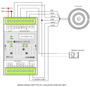
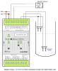
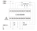
| Connection description |
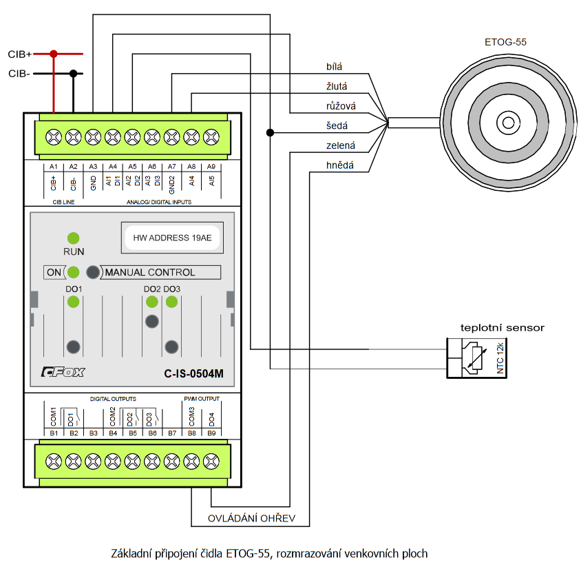
The power supply of the module is from the CIB bus. The CIB bus can have any topology and branching up to a distance of 500 m and up to 32 units on one CIB branch. The maximum consumption of all modules in one CIB branch is limited to 1A. Only a resistive element can be connected to analog inputs AI4, AI5. These inputs are suitable for resistance sensors sensing humidity or level, as they protect the sensors against galvanic corrosion. The maximum length of the wires for connecting the humidity sensor is 3m. An example of module connection is shown in the following figure. |
| Connection of power and system communication | connector with 2.5 mm2 screw terminal |
| Connection of inputs / outputs | connector with screw terminal 2.5 mm2 |
| Module operation | |
| Commissioning | The module is operated, set and diagnosed from the MOSAIC programming environment or other parameterization software. The module is ready for operation after connecting the supply voltage and the CIB bus. The HW address is indicated on the label on the module. |
| Module diagnostics | The basic diagnostics is performed internally and the result is available in the relevant registers of the Mosaic environment. The module contains an indication LED for checking the status of inputs / outputs. By pressing the Manual Control button, the module can be switched to manual mode and the individual outputs can be controlled. |
| Maintenance | |
| Description | The module does not require any maintenance under general installation conditions. |
| Notice | Because the module contains semiconductor components, it is necessary to follow the principles for working with electrostatic sensitive components when handling the removed cover. It is not allowed to directly touch the printed circuit boards without protective measures !!! |
| Warranty | |
| Generally | Warranty and complaint conditions are governed by the Terms and Conditions of Teco a.s. |
| Notice | You must meet all the conditions of this documentation before turning on the system. The system must not be put into service unless it has been verified and confirmed that the machinery meets the requirements of Directive 89/392 / EEC, in so far as it applies to it. Documentation subject to change. |
HW documentation
C-IS-0504M - Basic documentation
1.17 MB, (EN)
User manuals
Peripheral module on CIB-Common Installation Bus(R) (cs), TXV00413_01
14.01 MB
Peripheral modules on the CIB Common Installation Bus(R) (en), TXV00413_02
13.94 MB, (EN, RU, DE, UA)
Files for designers
Foxtrot 2 - library of elements in DXF and DWG formats, v. 2025/08.
21.80 MB
Foxtrot 2 - element library for SchemataCAD, v. 2025/08.
6.96 MB
EC - Declaration of Conformity
Foxtrot - EC Declaration of conformity
295.20 kB, (EN, RU, DE, UA)


ETOG + jímka
ETOG + jímka
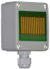
ETOG 55, Temperature-humidity sensor with thermowell for installation in concrete or asphalt, cable 10 m
- C-IS-0504M - ...s only intended to power these sensors with a power input about 2 W; the output circuits have no overload protection. The C-IS-0504M module is also equipped with 3 relay outputs, 1 x 16 A and 2 x 5 A, e.g. for switching heating cables for defrosti...
- The S-RS-01I precipitation detector with the C-IS-0504M module - ...ctor is designed to detect precipitation for automatic drawing of awnings or closing roof windows; it is connected to the C-IS-0504M module, which provides the power supply for the heating and measurement of the detector. The unused inputs and...
- Rain detector S-RS-01I with module C-IS-0504M - The S-RS-01I rain detector connected to the C-IS-0504M module, which provides power to the heating and the measurement of the detector, is intended for the detection of precipitation, eg for automatic retraction of awnings, closing of ro...
- Power dissipation of modules for calculation of switchboard heating - ...le for LED chips, controlled power supply C-DM-0006M-ILED 5,0 W TXN 133 49 C-IS-0504M; CIB, 3x AI/DI, 3x RO, 1x PWM (4W), 2x AI (AC resistance measurement) C-IS-0504M 2,0 W...
- Defrosting gutters, the ETOR-55 sensor - ...approx. 2.5 W at 24 V supply. Heating of the ETOR sensor can be switched by the system relay output, e.g. the output of the C-IS-0504M module, to which the ETOR sensors are also connected (a maximum of 2 sensors per separate module inputs) - see th...
- Defrosting outdoor spaces, the ETOG-55 sensor - ...wer input of approx. 2.5 W at 24 V supply. Heating of the ETOG-55 sensor can be connected directly to the DO4 output of the C-IS-0504M module , which is primary intended to power the heating.If the heating of the ETOG-55 sensor is powered from anoth...
- Submersible conductivity sensors - sensing of water level of electrically conductive liquids - The C-IS-0504M module can be used for monitoring water levels in the tanks, e.g. for control of irrigation systems, etc. Monitoring of level in water tanks by DC measurement of resistive sensor is not recommended due to the destruction of ele...
- Immersion conductivity probes - sensing the water level of electrically conductive liquids - The C-IS-0504M module can be used for monitoring the water level in tanks, eg for controlling irrigation systems, etc. For monitoring the water level in the tank, it is inappropriate to measure the conductivity (resistance) with direct current (as...
No data available.