
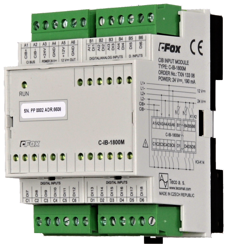
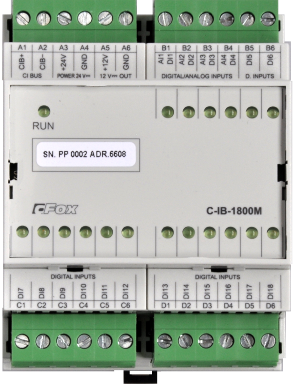
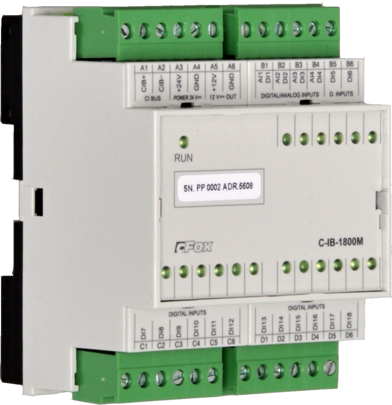
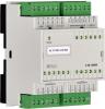
C-IB-1800MTXN 133 06
C-IB-1800M; CIB, 4x AI/DI universal inputs 14x DI including double balanced inputs, 4M
| DI | 14x DI |
|---|---|
| DI/AI | 4x DI/AI |
| DO | |
| AI | |
| AO | |
| COM | 1x CIB slave |
| SENSOR |
| Picture | Variant | Variant description |
|---|---|---|

|
C-IB-1800M |
C-IB-1800M is a module on the CIB bus, which contains a total of 18 inputs
- 14 binary inputs - mainly for sensing potential-free contacts
- These inputs can be switched to the so-called balanced input mode used for security sensors. In this mode, the inputs can also detect sensor disconnection as tamper
- The module also has a power supply for security sensors requiring 12V DC
- 4 combined AI / DI inputs not only for binary and balanced inputs, but also for measuring passive resistance / temperature sensors. These inputs can also be configured as fast pulse counters up to 1 kHz
- In installations where a higher proportion of input signals is usually directly from contacts and temperature sensors without the need for outputs for control or regulation
| Order num. | TXN 133 06 |
|---|---|
| Teco code | TXN 133 06 |
| Categories | CFox - Modules on DIN rail |
| Tags | - |
| COM - System buses | |
|---|---|
| CIB - Common Installation Bus (R): Installation I/O bus | 1x CIB slave |
| DI - Organization of binary inputs | |
| Total number of binary inputs | 18 |
| Number of groups of binary inputs | 2 |
| Organization of binary inputs into groups |
4x (AI/DI1 - AI/DI4) + 14x (DI5-DI18) Pulse counter up to 1kHz, standard S0 |
| DI - Parameters of binary inputs DC (group A) | |
| Parameters valid for inputs on the terminals | 4x (AI/DI1 - AI/DI4) |
| Number of inputs in group | 4 |
| Common wire | GND - module ground |
| Combined input type | DI / AI - measurement of resistance sensors, sensing of potential-free contacts and balanced loops |
| Galvanic isolation of inputs from internal/peripheral circuits | No |
| Diagnostics | indication of energized input by LED on module panel |
| DI - Parameters of DC binary inputs (group B) | |
| Parameters valid for inputs on the terminals | 14x (DI5-DI18) |
| Number of inputs in group | 14 |
| Common wire | GND - module ground |
| Combined input type | DI - Binary, balanced |
| Galvanic separation of inputs from internal circuits | No |
| Diagnostics | indication of energized input by LED on module panel |
| AI - Organization of analog inputs | |
| Total number of analog inputs | 4 |
| Number of inputs per group | 4 |
| Number of analog input groups | 1 |
| Organization of analog inputs into groups | 4x (AI/DI1 - AI/DI4) |
| Input type | With common clamp |
| Galvanic separation from internal circuits | No |
| Diagnostics | yes, signaling on the module panel and in status |
| AI - Analog Input Ranges (Group A) | |
| Passive sensor | Pt1000, W100 = 1,385 (-90 to +320 °C) |
| Passive sensor | Pt1000, W100 = 1,391 (-90 to +320 °C) |
| Passive sensor | Ni1000, W100 = 1,500 (–60 to +200 ° C) |
| Passive sensor | Ni1000, W100 = 1.617 (-60 to +200 ° C) |
| Passive sensor | Resistance transmitter 0-160 kOhm |
| Passive sensor | KTY81-121; PTC thermistor (-55 to + 125 °C) |
| Passive sensor | NTC Thermistor 12k / 25 °C (-40 to + 125 °C) |
| DI: Voltage-free contact | 0 when> 1.5 kOhm, 1 when <0.5 kOhm |
| DI: Balanced resistance input | Yes |
| Resistance measurement error - maximum error at 25 ° C | ± 0.5% of full scale |
| Power supply | |
| Supply voltage, tolerances | 24/27 V DC from CIB bus |
| Maximum power input | 4,5 W |
| Module thermal/power loss | 2 W |
| Maximum current consumption (mA) | 250 mA |
| Power supply from CIB - maximum current consumption (mA) | 160 mA |
| Galvanic separation of power supply from internal circuits | No |
| Power supply from CIB - Galvanic separation of power supply from internal circuits | No |
| Internal protection | Yes, PTC reversible fuse |
| Power supply from CIB - internal protection | Yes, returnable fuse |
| Size and weight | |
| Weight approx. | 150 g |
| Product dimensions (width x height x depth) | 70 х 90 х 58 mm |
| Module width in multiples of M (17.5 mm) | 4M |
| Module width | 70 mm |
| Module height | 90 mm |
| Module depth | 58 mm |
| Operating conditions, product standards | |
| Product standard | ČSN EN 60730-1 ed. 2:2001 (mod IEC 60730-1:1999) |
| Protection class of electrical object | I, according to ČSN EN 61140 ed.3: 2016 (idt IEC 61140:2016) |
| IP rating (Ingress Protection) according to ČSN EN 60529: 1993 (idt IEC 529: 1989) | IP10B |
| Operating areas | Normal according to ČSN 33 2000-1: 2003 (IEC 364-1: 1992 mod) |
| Degree of pollution | 1, according to ČSN EN 60664-1 ed.2:2008 ( idt IEC 60664-1:2007) |
| Overvoltage category installation | II, according to EN 60664-1 ed_2: 2008 (idt IEC 60641-1: 2007) |
| Type of device | Module on DIN rail |
| Working position | Vertical |
| Type of operation (operating frequency) | Continuous |
| Ambient operating temperatures | -10 °C to + 55 °C |
| Operating temperature maximum (° C) | +55°C |
| Operating temperature minimum (° C) | -20°C |
| Operating relative humidity | from 10 % up to 95 % without condensation |
| Operating atmospheric pressure | min. 70 kPa (<3,000 m above sea level) |
| Storage temperatures | –25 °C to +70 °C |
| Electromagnetic compatibility, Mechanical endurance | |
| Electromagnetic compatibility / Emission | ČSN EN 55022 ed2:2007 (mod CISPR22:2005) |
| Electromagnetic compatibility / Immunity | min. according to ČSN EN 60730-1 ed.2: 2001 |
| Sinusoidal vibration endurance | 10 Hz to 57 Hz, amplitude 0,075 mm, 57 Hz to 150 Hz, acceleration 1 G (Fc test according to EN 60068-2-6: 1997 (idt IEC 68-2-6: 1995), 10 cycles per axis.) |
| Packaginng, transportation, storage | |
| Description | The module is packed in a paper box. This documentation is also part of the package. The outer packaging is carried out according to the scope of the order and the method of transport in a transport package provided with labels and other data necessary for transport. The product must not be exposed to direct weather conditions during transport and storage. Malting of the product is only allowed in clean rooms without conductive dust, aggressive gases and vapors. The most suitable storage temperature is 20 ° C |
| Installation | |
| Assembly description | Mounting on DIN rail 35 / 7.5 (U) in the switchboard |
| Attention! | The modules contain components sensitive to electrostatic charge, so we observe them principles for working with these circuits! We handle only on the module disconnected from the power supply! When replacing the submodules, the correctness of the deployment must be carefully checked of the submodule cavities against the tips on the motherboard. The tubes have no coding position and incorrect installation, may occur when the power is turned on again damage to the submodule or even the motherboard !!! |
| Connection | |
| Connection of power and system communication | connector with 2.5 mm2 screw terminal |
| Connection of inputs / outputs | connector with screw terminal 2.5 mm2 |
| CIB connection | connector with 2.5 mm2 screw terminal |
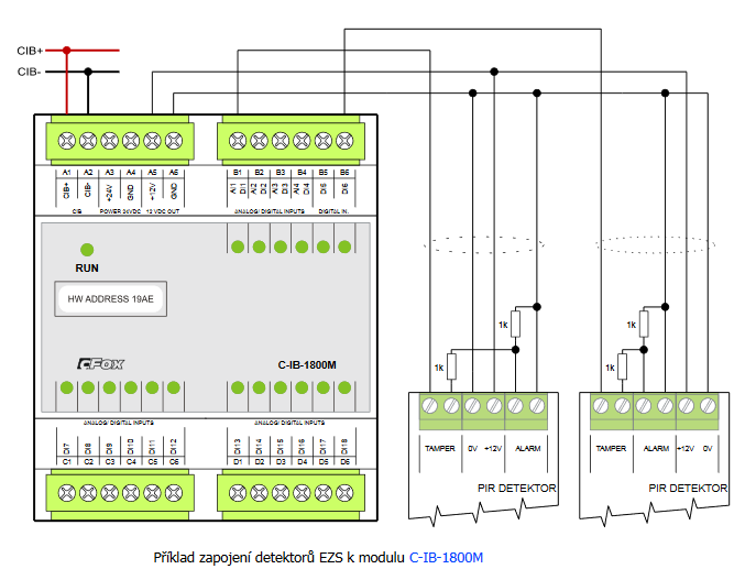
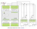
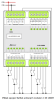
| Connection description | An example of module connection is shown in the following figure. |
| Module operation | |
| Commissioning | The module is operated, set and diagnosed from the MOSAIC programming environment or other parameterization software. The module is ready for operation after connecting the supply voltage and the CIB bus. The HW address is indicated on the label on the module. |
| Module diagnostics | The basic diagnostics is performed internally and the result is available in the relevant registers of the Mosaic environment. |
| Maintenance | |
| Description | The module does not require any maintenance under general installation conditions. |
| Notice | Because the module contains semiconductor components, it is necessary to follow the principles for working with electrostatic sensitive components when handling the removed cover. It is not allowed to directly touch the printed circuit boards without protective measures !!! |
| Warranty | |
| Generally | Warranty and complaint conditions are governed by the Terms and Conditions of Teco a.s. |
| Notice | You must meet all the conditions of this documentation before turning on the system. The system must not be put into service unless it has been verified and confirmed that the machinery meets the requirements of Directive 89/392 / EEC, in so far as it applies to it. Documentation subject to change. |
HW documentation
C-IB-1800M - Basic documentation
1.29 MB, (EN)
User manuals
Peripheral module on CIB-Common Installation Bus(R) (cs), TXV00413_01
14.01 MB
Peripheral modules on the CIB Common Installation Bus(R) (en), TXV00413_02
13.94 MB, (EN, RU, DE, UA)
Files for designers
Foxtrot 2 - library of elements in DXF and DWG formats, v. 2025/08.
21.80 MB
Foxtrot 2 - element library for SchemataCAD, v. 2025/08.
6.96 MB
EC - Declaration of Conformity
Foxtrot - EC Declaration of conformity
295.20 kB, (EN, RU, DE, UA)
- C-IB-1800M - The C-IB-1800M is a module on a CIB bus; it has 14 binary inputs, which can be configured in the mode of the balanced loop evaluation (for ESS detectors ), and 4 universal AI/DI inputs, any of which can be adjusted to one of the followin...
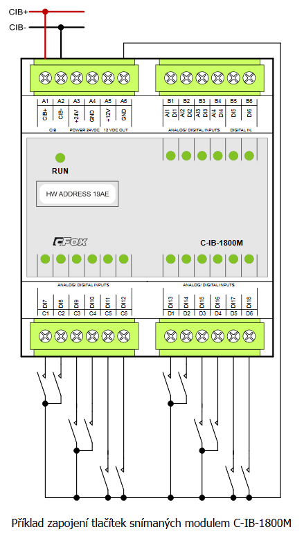
- The push-buttons scanned by the C-IB-1800M module in the control panel - ...meters, flowmeters, etc. For more information about powering, maximum power consumption, etc., see the article about the C-IB-1800M module. Fig. 1. An example of connecting the push-buttons scanned by the C-IB-1800M module...
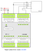
- Connecting PIR detectors with double-balanced loop to the C-IB-1800M module - The C-IB-1800M module is suitable for installations where the customer prefers the star configuration of ECC detectors connection - i.e. a cable leads from each detector to the control panel for the power supply and evaluation of the detector...
- Power dissipation of modules for calculation of switchboard heating - ...0008M; CIB, 8x RO, switching contact, 230V/16A C-OR-0008M 4,0 W TXN 133 06 C-IB-1800M; CIB, 4x AI/DI universal inputs, 14xDI including double-balanced, 4M C-IB-1800M 2,0 W...
- CIB power supply – principles, optimization - ...the C-HM-1121M , which are powered from 230VAC, or the C-OR-0008M , C-OR-0011M-800 , C-JC-0006M and C-IB-1800M , which can be optionally powered from a 24 or 27 VDC external power supply, in which case they do not load the...
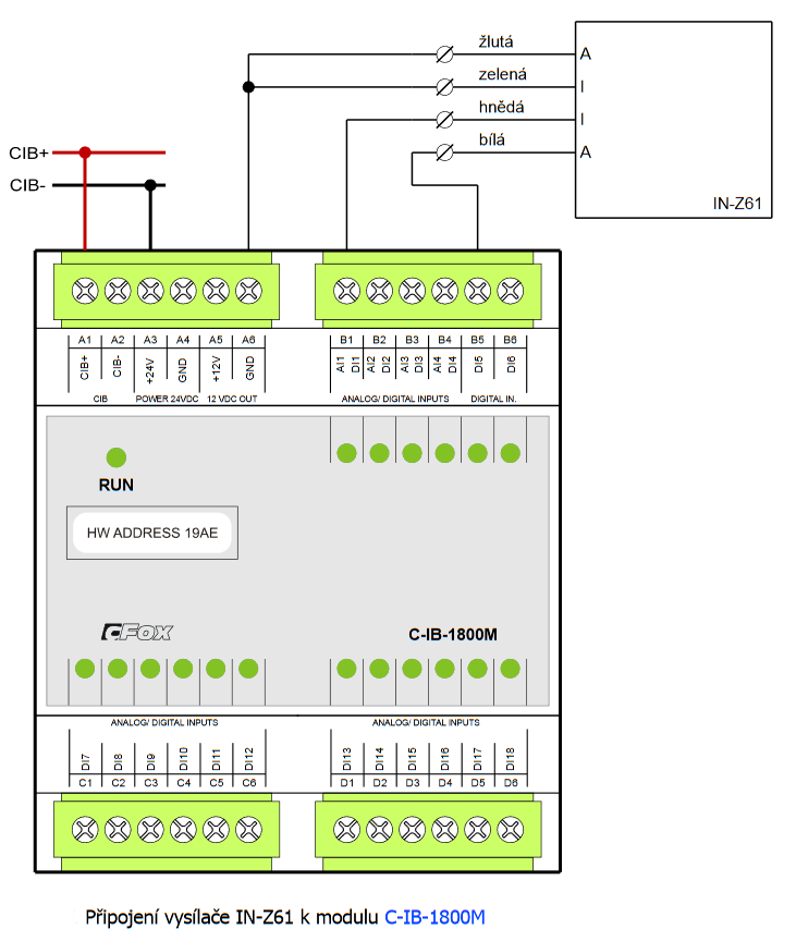
- Metering the consumption, the Elster gas meters - ...around 0.25 s Fig. .1 Wiring the IN-Z61 transmitter to the C-IB-1800M module Notes: The transmitter is equipped with an RJ connector, where the cable...
- The separate temperature sensor S-TS-01R, connected to the AI of the system - ...ure sensor can also be connected to any input of the system with an appropriate range, e.g. the AI1 to AI4 inputs of the C-IB-1800M module , the AI1 to AI3 inputs of the modules C-HM-0308M , C (R) -HM-1113M and C (R) -HM-1121M ....
- Connecting an indoor siren - ...(here it is single balanced ), you should use a different DI system input, which supports balanced inputs (e.g. the C-IB-1800M module input), or you can also use the input to CP 1000 , which should be measured as AI; a 1 kΩ...
- Emergency lighting - LED strip with module C-WG-0503S - For easy-to-implement emergency lighting, we can use the C-WG-0503S , module, which will provide us with 12 VDC power supply and control (binary output) for LED strips, which can be fitted into a standard lamp. E.g. 5 cm of ordinary LED str...
- Conection of the opening detectors - There are a number of devices available for monitoring of the opening of doors, which differ primarily in their mechanical design and the purpose. Some recommended types are described below. When installing the detectors (magnetic conta...
- Connecting the IMPAQ Glass Break detector to the C-WG-0503S module - The IMPAQ Glass Break detector can be used for the detection of breaking glass; it is manufactured by the TEXECOM . It is a digital acoustic glass break detector with digital sound processing, designed for sheet, laminated, hardened, tempered,...
- Connecting exterior motion detectors (PIR) to the C-WG-0503S module - We recommend the basic variants of the Elite detectors, the TEXECOM and Tecnoalarm manufacturers for outdoor applications of motion detectors (the perimeter protection). The Elite-EXT-TD-B detector is a PIR scanner with two...
- Connecting interior motion detectors (PIR) to the C-WG-0503S module - The usage of interior motion detectors varies according to the type of protected areas, access of animals in the armed status, the size of the areas, etc. There are a number of manufacturers and types of detectors on the market. Possible recommende...
No data available.