


C-FC-0024XTXN 133 39
C-FC-0024X; CIB, I/O for Fan Coil, 0-100% fan speed control 24V, 3x AI/DI, 2x RO
| DI | |
|---|---|
| DI/AI | 3x DI/AI |
| DO | 2x RO |
| AI | |
| AO | 1x AO |
| COM | 1x CIB slave |
| SENSOR |
| Picture | Variant | Variant description |
|---|---|---|

|
C-FC-0024X |
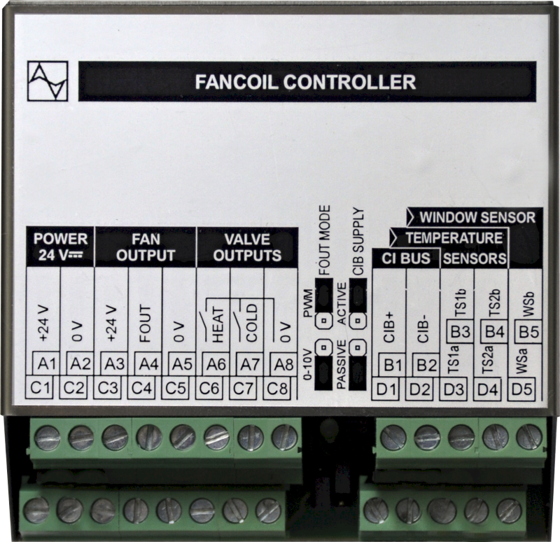
Modules C-FC-0024X is a composition of inputs and outputs designed to control the valves and fan of the FanCoil unit. If the composition of inputs and outputs is satisfactory, it can be used universally. The module contains 3 combined (analog / binary) inputs with a common terminal for connecting contacts or resistors.
sensors, 1 analog / PWM output (8 bits, 0-10V) for continuous fan speed control and 2 relay outputs with a common terminal for controlling valves with heating and cooling water. The module is equipped with screwed terminal blocks.
The module is designed for DIN rail. The metal cover allows the module to be built directly into the floor Fan Coil, for example. It is connected to the Foxtrot basic module via a two-wire CIB Common Installation Bus®.
| Order num. | TXN 133 39 |
|---|---|
| Teco code | TXN 133 39 |
| Categories | CFox - Modules on DIN rail |
| Tags | - |
| COM - System buses | |
|---|---|
| CIB - Common Installation Bus (R): Installation I/O bus | 1x CIB slave |
| DI - Parameters of binary inputs DC (group A) | |
| Parameters valid for inputs on the terminals | DI1/AI1 - DI3/AI3 |
| Number of inputs in group | 3 |
| Common wire | plus |
| Combined input type | DI/AI Active, for sensing potential-free contacts and measuring resistance sensors |
| Galvanic isolation of inputs from internal/peripheral circuits | No |
| Diagnostics | signaling of excited input in Mosaic |
| Pulse input overload capacity | max. 30 V (t < 10 ms) |
| Input voltage | 3.3 V from internal source |
| Input current at log. 1 (typ.) | 0.35 mA typ. |
| Delay from log. 0 to log. 1 | 5 ms |
| Delay from log. 1 to log. 0 | 5 ms |
| The minimum width of the captured pulse | 5 ms |
| RO - Parameters of binary relay outputs (group A) | |
| Number of relay outputs | 2 |
| Output type | electromechanical relay, unprotected output |
| Contact type | NO - Normally Open |
| Galvanic separation from internal circuits | Yes |
| Switching current | 1 A max. 100 mA min. |
| Switching voltage | 30 V DC max. |
| Short-term output overload - inrush | 2 A max. |
| Current through common clamp | 4 A max. |
| Contact closing time | typ. 10 ms |
| Contact opening time | typ. 4 ms |
| Switching frequency without load | max. 300 switching / min. |
| Switching frequency with rated load | max. 20 switching / min. |
| Mechanical life | min. 5,000,000 cycles |
| Electrical life at maximum resistive load | min. 100,000 cycles |
| Electrical life at maximum load inductive DC13 | min. 100,000 cycles |
| Short-circuit protection | No |
| Treatment of inductive load | External RC element, varistor (AC), diode (DC) |
| AI - Organization of analog inputs | |
| Total number of analog inputs | 3 |
| Input type | With common clamp |
| Common wire | Plus |
| Galvanic separation from internal circuits | No |
| Diagnostics | overload signaling in status word |
| External power supply | No |
| Converter type | Approximation |
| Analog input error - Temperature coefficient | ± 0,1% of full scale/K |
| Analog input error - Steady state repeatability | ± 0,5% of full scale |
| AI - Analog Input Ranges (Group A) | |
| Passive sensor | NTC Thermistor 12k / 25 °C (-40 to + 125 °C) |
| DI: Voltage-free contact | 0 when> 1.5 kOhm, 1 when <0.5 kOhm |
| AO - Analog output parameters | |
| Galvanic isolation from internal circuits | No |
| Converter resolution | 8 bit |
| conversion time | 10 μs |
| Analog output error - maximum error at 25 ° C | ± 2% of full scale |
| Analog output error - temperature coefficient | ± 0.3% of full scale / K |
| Analog output error - linearity | ± 0.7% of full scale |
| Analog output error - repeatability under steady state conditions | ± 0.5% of full scale |
| Voltage output - voltage | 0 - 10,5 V |
| Voltage output - Resolution 1 LSB | 10,546 mV |
| Voltage output - maximum output current | 10 mA |
| Size and weight | |
| Weight approx. | 100 g |
| Product dimensions (width x height x depth) | 82,7 x 80,8 x 32 mm |
| Packaginng, transportation, storage | |
| Description | The module is packed in a paper box. This documentation is also part of the package. The outer packaging is carried out according to the scope of the order and the method of transport in a transport package provided with labels and other data necessary for transport. The product must not be exposed to direct weather conditions during transport and storage. Malting of the product is only allowed in clean rooms without conductive dust, aggressive gases and vapors. The most suitable storage temperature is 20 ° C |
| Installation | |
| Assembly description | The module is mounted in a vertical position on the U-rail ČSN EN 50022. Installation of the assembly (basic module and possibly peripheral modules) is performed according to TXV 004 13. |
| Connection | |
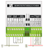
| Connection description |
The modules are implemented as standard units on a two-wire CIB bus, which ensures communication and power supply of the entire module. The CIB bus can have any topology and branching up to a distance of 500 m and up to 32 units on one CIB branch. The CIB bus master is the FOXTROT base unit or the CF-1141 module. Further information can be found in the manual Peripheral modules on the CIB TXV 004 13. |
| Connection of power and system communication | terminal block with screw terminal 2.5 mm2 |
| Connection of inputs / outputs | terminal block with screw terminal 2.5 mm2 |
| Module installation tools | (-) 3 mm, flat screwdriver |
| Module operation | |
| Module configuration | The module is configured using jumpers. The "FOUT MODE" jumper allows you to select the FOUT output type. The output can be configured as a standard 0 ÷ 10V analog output or a PWM output. The "CIB SUPPLY" jumper is used to activate the CIB bus supply. If the bus supply is set to "ACTIVE", the module provides the supply voltage for the CIB bus. |
| Commissioning | The module is operated, set and diagnosed from the MOSAIC programming environment or other parameterization software. The module is ready for operation after connecting the supply voltage and the CIB bus. The HW address is indicated on the label on the module. |
| Maintenance | |
| Description | The module does not require any maintenance under general installation conditions. The operations in which a part of the module has to be dismantled must always be carried out with the supply voltage disconnected. |
| Notice | Because the module contains semiconductor components, it is necessary to follow the principles for working with electrostatic sensitive components when handling the removed cover. It is not allowed to directly touch the printed circuit boards without protective measures !!! |
| Warranty | |
| Generally | Warranty and complaint conditions are governed by the Terms and Conditions of Teco a.s. |
| Notice | You must meet all the conditions of this documentation before turning on the system. The system must not be put into service unless it has been verified and confirmed that the machinery meets the requirements of Directive 89/392 / EEC, in so far as it applies to it. Documentation subject to change. |
HW documentation
C-FC-0024X- Basic documentation
122.70 kB
User manuals
Peripheral module on CIB-Common Installation Bus(R) (cs), TXV00413_01
14.01 MB
Peripheral modules on the CIB Common Installation Bus(R) (en), TXV00413_02
13.94 MB, (EN, RU, DE, UA)
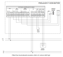
Scheme
C-FC-0024X
34.41 kB
Files for designers
C-FC-0024X Technical drawing M01 DWG
81.88 kB
C-FC-0024X Technical drawing M02 DXF
160.58 kB
C-FC-0024X Technical drawing S01 DWG
60.88 kB
C-FC-0024X Technical drawing S02 DXF
74.87 kB
EC - Declaration of Conformity
Foxtrot - EC Declaration of conformity
295.20 kB, (EN, RU, DE, UA)
- Ventilation and recuperation units - ...C-FC-0230X Continuous regulation of 24 VDC EC motors, a built-in version C-FC-0024X Continuous regulation of 24 VDC EC motors , 0÷10 V control...
- Control of floor convectors (e.g. ISAN) with the EC 24 VDC motors - The C-FC-0024X enables controlling of several convectors fitted with 24 V EC motors (analogue 0 ÷ 10 V control or PWM), controlling up to two electric drives (hot and cold water), measuring up to 3 temperatures (each input can be configured f...
No data available.