

C-OS-0808MTXN 133 96
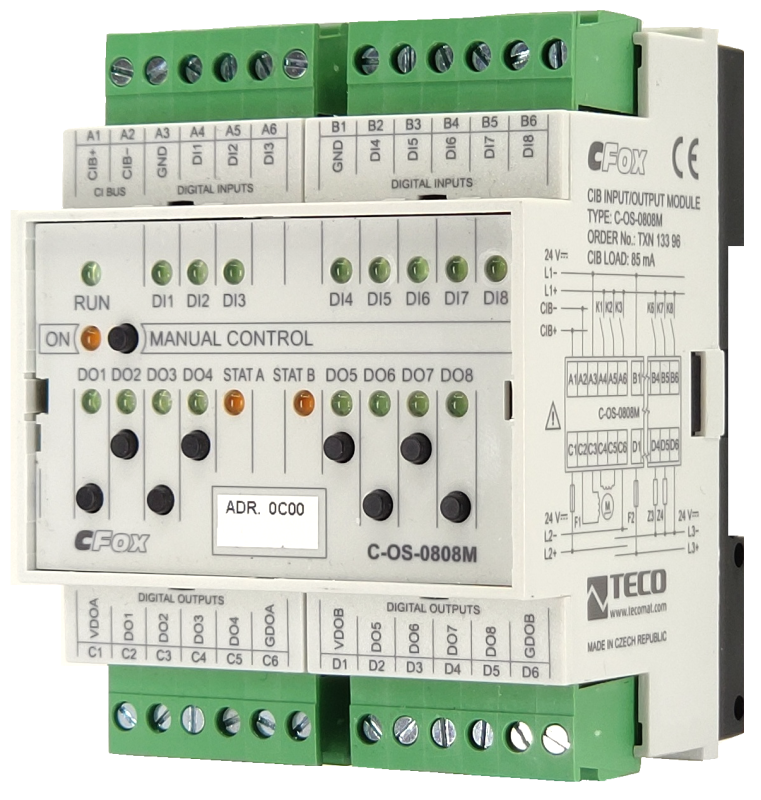
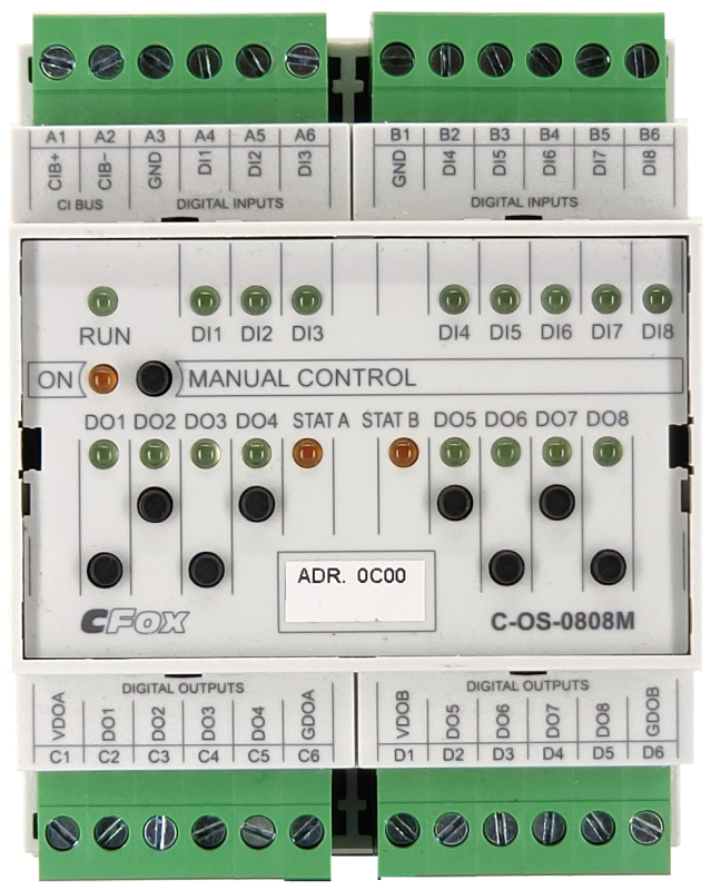
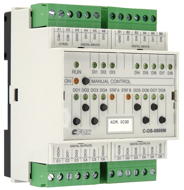
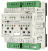
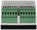
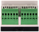
C-OS-0808M; CIB, 8x input 24 V DC, 8x fast transistor output 24 V DC; Control of 2 stepper motors
| DI | 8x DI (3+5) |
|---|---|
| DI/AI | |
| DO | 8x DO (4+4) |
| AI | |
| AO | |
| COM | 1x CIB slave |
| SENSOR |
| Picture | Variant | Variant description |
|---|---|---|

|
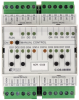
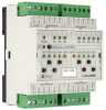
C-OS-0808M |
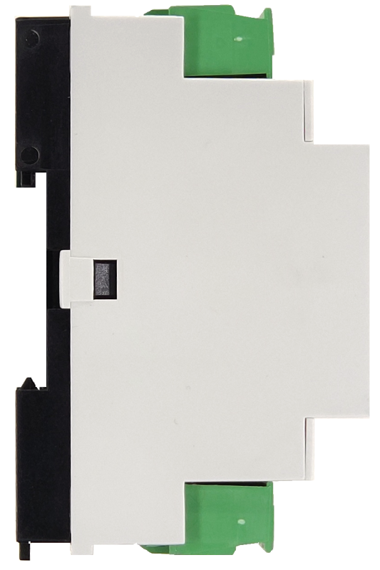
Expansion module C-OS-0808M with 8 binary inputs at the level of 24 V DC and 2x4 fast transistor outputs usable for direct control of two unipolar or bipolar stepper motors. Inputs and outputs can also be used universally and can be set manually
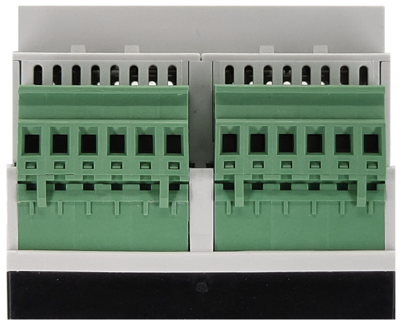
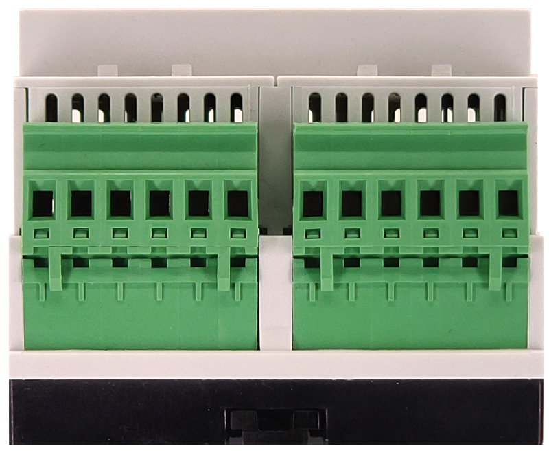
mode with the buttons on the front panel. The module is equipped with removable screw connectors.
The module is designed for a DIN rail switchboard. It is connected to the Foxtrot basic module via a two-wire CIB Common Installation Bus®.
mode with the buttons on the front panel. The module is equipped with removable screw connectors.
The module is designed for a DIN rail switchboard. It is connected to the Foxtrot basic module via a two-wire CIB Common Installation Bus®.
| Order num. | TXN 133 96 |
|---|---|
| Teco code | TXN 133 96 |
| Categories | CFox - Modules on DIN rail |
| Tags | - |
| COM - System buses | |
|---|---|
| CIB - Common Installation Bus (R): Installation I/O bus | 1x CIB slave |
| DI - Organization of binary inputs | |
| Total number of binary inputs | 8 |
| Number of groups of binary inputs | 2 |
| Organization of binary inputs into groups | 3x (DI1-DI3) + 5x (DI4-DI5) |
| DI - Parameters of binary inputs DC (group A) | |
| Number of inputs in group | 8 |
| Common wire | minus |
| Galvanic isolation of inputs from internal/peripheral circuits | No |
| Diagnostics | indication of energized input by LED on module panel |
| Pulse input overload capacity | max. 30 V (t < 10 ms) |
| Input voltage for log. 0 | 0 V DC; -5 V DC min.; +5 V DC max. |
| Input voltage for log. 1 | 24 V DC; 15 V DC min.; 30 V DC max. |
| Input current at log. 1 (typ.) | 5 mA at 24 V DC |
| Delay from log. 0 to log. 1 | 5 ms |
| Delay from log. 1 to log. 0 | 5 ms |
| DO/RO - Organization of binary outputs | |
| Total number of binary outputs | 8 |
| Number of binary output groups | 2 |
| DO - Parameters of binary transistor outputs (group A) | |
| Number of transistor outputs | 8 |
| Number of output groups | 2 |
| Number of outputs in group | 4 |
| Output type | Bipolar, unipolar |
| Galvanic separation from internal circuits | Yes |
| Switching voltage | 8 - 32 V DC; Supply voltage (VDDA, VDDB) |
| Insulation voltage between outputs and internal circuits | 500 V |
| Insulation voltage between input and output groups | 500 V |
| DO - Bipolar outputs | |
| Type of semiconductor outputs | Half H bridge |
| Supply voltage (VDDA, VDDB) - switched voltage L2 | 8 – 32 V DC |
| Switching current | max. 2.0 A, pulse 4 A |
| Total switched group current at ambient temperature 25 ° C (VDDA, VDDB) | < 6 A |
| Total switched group current at ambient temperature 50 ° C (VDDA, VDDB) | < 4 A |
| Residual current (blocked outputs) | max. 2 mA |
| Output resistance | 0,3 Ω typ. - 0,6 Ω max. |
| Switching time | 1,6 μs typ. |
| Opening time | 0,6 μs typ. |
| Short circuit protection | Yes |
| DO - Unipolar outputs | |
| Type of semiconductor outputs | Open collector |
| Supply voltage (VDDA, VDDB) - switched voltage L2 | 8 – 32 V DC |
| Switching current of individual output | max. 2,0 A |
| Total switched group current at ambient temperature 25 ° C (GDOA, GDOB) | < 6 A |
| Total switched group current at ambient temperature 50 ° C (GDOA, GDOB) | < 4 A |
| Residual current (blocked outputs) | max. 0,1 mA |
| Output saturation voltage | Typ. 0,25 V (Iout = 1 A) |
| Switching time | 20,0 μs typ. |
| Opening time | 20,0 μs typ. |
| Short circuit protection | No |
| Power supply | |
| Supply voltage, tolerances | 24 V DC, +25%, -15%, SELV |
| Power supply from CIB - voltage | 24/27 V DC |
| Maximum power input | 2,5 W |
| Module thermal/power loss | 5 W |
| Maximum current consumption (mA) | 85 mA |
| Galvanic separation of power supply from internal circuits | No |
| Internal protection | Yes, PTC reversible fuse |
| Size and weight | |
| Weight approx. | 150 g |
| Product dimensions (width x height x depth) | 70 х 90 х 58 mm |
| Operating conditions, product standards | |
| Product standard | ČSN EN 60730-1 ed.4 :2017 (EN 60730-1:2016) -Automatic electronic control device (for household and similar purposes) |
| Protection class of electrical object | III, according to ČSN EN 61140 ed.3: 2016 (idt IEC 61140:2016) |
| IP rating (Ingress Protection) according to ČSN EN 60529: 1993 (idt IEC 529: 1989) | IP20 |
| Operating areas | Normal, acc. ČSN 33 2000-1 ed.2: 2009 (mod IEC 60354-1:2005) |
| Degree of pollution | 2, according to ČSN EN 60664-1 ed.2: 2008 (idt IEC 60664-1: 2007) |
| Overvoltage category installation | II, according to EN 60664-1 ed_2: 2008 (idt IEC 60641-1: 2007) |
| Type of device | Module on DIN rail |
| Working position | Vertical |
| Type of operation (operating frequency) | Continuous |
| Ambient operating temperatures | -10 °C to + 55 °C |
| Operating relative humidity | from 10 % up to 95 % without condensation |
| Operating atmospheric pressure | min. 70 kPa (<3,000 m above sea level) |
| Storage temperatures | –25 °C to +70 °C |
| Electromagnetic compatibility, Mechanical endurance | |
| Electromagnetic compatibility / Emission | B, according to EN 55032 ed. 2: 2017 (idt CISPR 32: 2015) |
| Electromagnetic compatibility / Immunity | min. according to ČSN EN 60730-1 ed.3: 2012 |
| Sinusoidal vibration endurance | 10 Hz to 57 Hz, amplitude 0,075 mm, 57 Hz to 150 Hz, acceleration 1 G (Fc test according to EN 60068-2-6: 1997 (idt IEC 68-2-6: 1995), 10 cycles per axis.) |
| Packaginng, transportation, storage | |
| Description | The module is packed in a paper box. This documentation is also part of the package. The outer packaging is carried out according to the scope of the order and the method of transport in a transport package provided with labels and other data necessary for transport. The product must not be exposed to direct weather conditions during transport and storage. Malting of the product is only allowed in clean rooms without conductive dust, aggressive gases and vapors. The most suitable storage temperature is 20 ° C |
| Installation | |
| Assembly description | The module is mounted in a vertical position on the U-rail ČSN EN 50022. Installation of the assembly (basic module and possibly peripheral modules) is performed according to TXV 004 13. |
| Connection | |
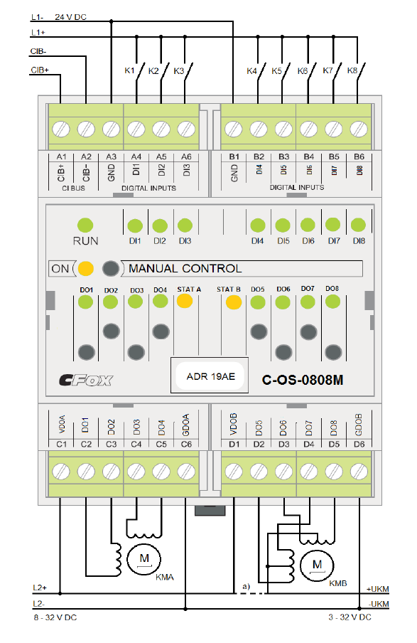
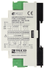
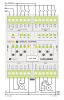
| Connection description |
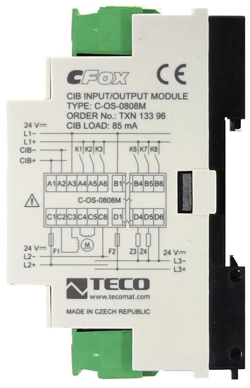
Wiring notes (Fig.1): The outputs (VDDA-GNDA and VDDB-GNDB) can be powered from each other source or from the same together with the system supply +24 V PLC. Internally, the groups are galvanically separated from each other and from the internal circuits. The supply of the winding of the unipolar stepper motor - UKM can be in the range of 3 - 32 V DC. If it is higher than 8 V DC, it can also be used to supply the output circuit of the respective channel. |
| Connection of power and system communication | connector with 2.5 mm2 screw terminal |
| Connection of inputs / outputs | connector with screw terminal 2.5 mm2 |
| Module installation tools | (-) 3 mm, flat screwdriver |
| Module operation | |
| Module configuration | The module is operated, set up and diagnosed from the Mosaic development environment. |
| Commissioning | The module is operated, set and diagnosed from the MOSAIC programming environment or other parameterization software. The module is ready for operation after connecting the supply voltage and the CIB bus. The HW address is indicated on the label on the module. |
| Module diagnostics | The basic diagnostic system of the module is part of its standard software. It has been in operation since the module power was turned on and works independently of the user. Diagnosed error states of the module and connected peripheral modules of the assembly are signaled in the status word of the module and on the module panel |
| Maintenance | |
| Description | The module does not require any maintenance under general installation conditions. The operations in which a part of the module has to be dismantled must always be carried out with the supply voltage disconnected. |
| Notice | Because the module contains semiconductor components, it is necessary to follow the principles for working with electrostatic sensitive components when handling the removed cover. It is not allowed to directly touch the printed circuit boards without protective measures !!! |
| Warranty | |
| Generally | Warranty and complaint conditions are governed by the Terms and Conditions of Teco a.s. |
| Notice | You must meet all the conditions of this documentation before turning on the system. The system must not be put into service unless it has been verified and confirmed that the machinery meets the requirements of Directive 89/392 / EEC, in so far as it applies to it. Documentation subject to change. |
HW documentation
C-OS-0808M Basic documentation
1.17 MB, (EN)
User manuals
Peripheral module on CIB-Common Installation Bus(R) (cs), TXV00413_01
14.01 MB
Peripheral modules on the CIB Common Installation Bus(R) (en), TXV00413_02
13.94 MB, (EN, RU, DE, UA)
Files for designers
Foxtrot 2 - library of elements in DXF and DWG formats, v. 2025/08.
21.80 MB
Foxtrot 2 - element library for SchemataCAD, v. 2025/08.
6.96 MB
EC - Declaration of Conformity
Foxtrot - EC Declaration of conformity
295.20 kB, (EN, RU, DE, UA)
- C-OS-0808M - The module contains 8 binary inputs and 8 transistor outputs. The outputs are primarily intended for direct control of up to two stepper motors. Alternatively, the transistor outputs can be used as standard binary outputs, or it is possible to activ...
- Power dissipation of modules for calculation of switchboard heating - ...C-1W-4000M; 1Wire bus master for 40 sensors C-1W-4000M 1,5 W TXN 133 96 C-OS-0808M; CIB, Stepper motor control - 2 channels, 8x 24 V output C-OS-0808M 5,0 W...
No data available.