


C-EV-0302MTXN 133 85
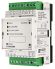
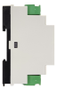
C-EV-0302M; Module for controlling AC charging an electric vehicle; PP, CP, 2x AI/DI, 1x DI (for S0), 1x RO, 1x DO
| DI | 1x DI |
|---|---|
| DI/AI | 2x DI/AI |
| DO | 1x DO 1x RO |
| AI | |
| AO | |
| COM | 1x CIB slave |
| SENSOR |
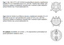
| Picture | Variant | Variant description |
|---|---|---|

|
C-EV-0302M |
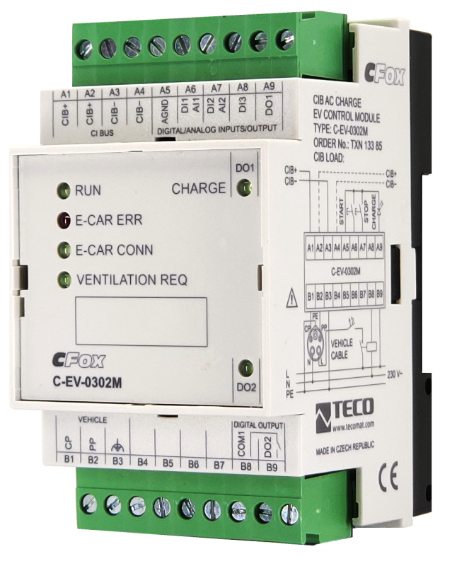
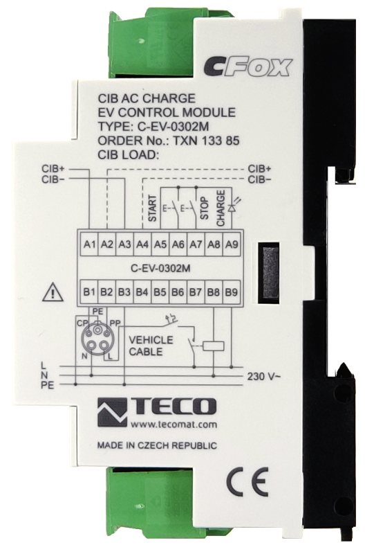
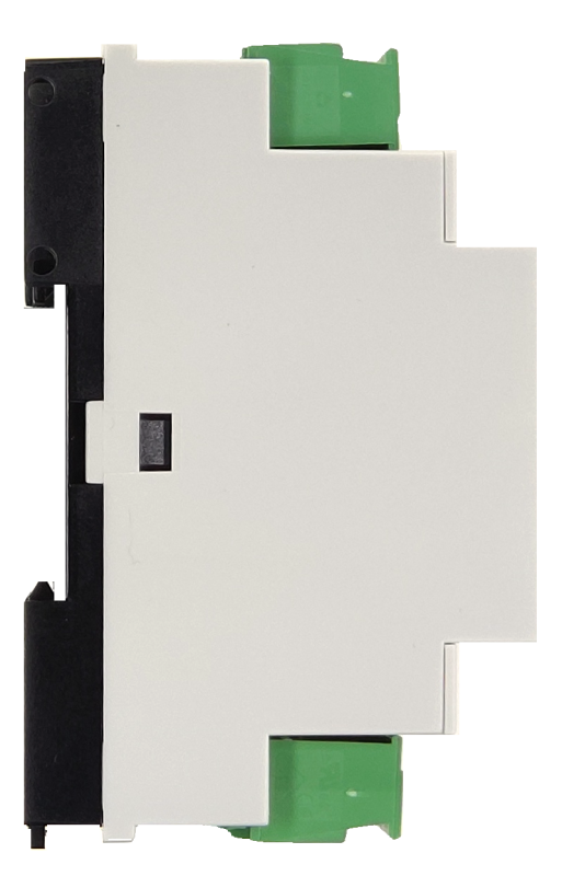
The C-EV-0302M module is intended for controlling the charging of electric vehicles with alternating current according to ČSN EN 61851-1. For charging control and feedback, the module contains CP (Control Pilot) and PP (Proximity function) outputs connected to the charging connector (Type 1, Type 2). Furthermore, the module contains a relay output for controlling the contactor of the power supply to the electric vehicle and one semiconductor output for connection with an external charging signal. The module also contains 2 universal AI / DI inputs and one counter input for counting pulses via the S0 interface from the electricity supply meter.
The module is designed for a DIN rail switchboard. It is connected to the Foxtrot basic module via a two-wire CIB Common Installation Bus®.
The module is designed for a DIN rail switchboard. It is connected to the Foxtrot basic module via a two-wire CIB Common Installation Bus®.
| Order num. | TXN 133 85 |
|---|---|
| Teco code | TXN 133 85 |
| Categories | CFox - Modules on DIN rail |
| Tags | Sales and production discontinued |
| COM - System buses | |
|---|---|
| CIB - Common Installation Bus (R): Installation I/O bus | 1x CIB slave |
| DI - Parameters of binary inputs DC (group A) | |
| Number of inputs in group | 1 |
| Combined input type | DI - Binary, balanced, pulse counter S0 |
| Galvanic isolation of inputs from internal/peripheral circuits | Yes |
| Max. measuring voltage on the connected contact | 15 V DC |
| Internal input resistance | 3,3 kΩ |
| Max. resistance for closed contact, log. 1 | < 0,8 kΩ |
| Min. resistance for open contact, log. 0 | > 4,2 kΩ |
| Balanced resistance input | 1x <3,3 kΩ (tamper/0/1/tamper) |
| DO - Parameters of binary transistor outputs (group A) | |
| Number of transistor outputs | 1 |
| Number of outputs in group | 1 |
| Output type | Semiconductor |
| Galvanic separation from internal circuits | Yes |
| Output voltage | 15 V DC |
| Output current | 20 mA |
| Short circuit protection | Yes |
| RO - Parameters of binary relay outputs (group A) | |
| Number of relay outputs | 1 |
| Number of outputs in group | 1 |
| Output type | electromechanical relay, unprotected output |
| Contact type | NO - Normally Open |
| Galvanic separation from internal circuits | Yes |
| Diagnose | Alarm signaling on panel module |
| Switching current | 6 A max. for 250 V AC; 5 A max. for 30 V DC |
| Switching voltage | 400 V AC max., 30 V DC max. |
| Switching power | 1500 VA max for AC, 150 W max for DC |
| Short-term output overload - inrush | 15 A max. (10 ms max.) |
| Contact closing time | typ. 10 ms |
| Contact opening time | typ. 5ms |
| Mechanical life | min. 30,000,000 cycles |
| Short-circuit protection | No |
| Treatment of inductive load | External RC element, varistor (AC), diode (DC) |
| Insulation voltage between outputs and internal circuits | 4000 V AC |
| Isolation voltage between groups of outputs to each other | 4000 V AC |
| Insulation voltage between contacts | 1000 V AC |
| AI - Analog Input Ranges (Group A) | |
| Voltage | 0-2 V |
| Voltage input error - max. error at 25 ° C | ± 2.0% of full scale |
| Passive sensor | Pt1000, W100 = 1,385 (-90 to +320 °C) |
| Passive sensor | Pt1000, W100 = 1,391 (-90 to +320 °C) |
| Passive sensor | Ni1000, W100 = 1,500 (–60 to +200 ° C) |
| Passive sensor | Ni1000, W100 = 1.617 (-60 to +200 ° C) |
| Passive sensor | Resistance transmitter 0-100 kOhm |
| Passive sensor | KTY81-121; PTC thermistor (-55 to + 125 °C) |
| Passive sensor | NTC Thermistor 12k / 25 °C (-40 to + 125 °C) |
| DI: Voltage-free contact | 0 when> 1.5 kOhm, 1 when <0.5 kOhm |
| DI: Balanced resistance input | 2x 1k1 (tamper/0/1/tamper) |
| Resistance measurement error - maximum error at 25 ° C | ± 2% of full scale |
| Power supply | |
| Supply voltage, tolerances | 24 V DC, +25%, -15%, SELV |
| Power supply from CIB - voltage | 24/27 V DC |
| Maximum power input | 2 W |
| Power supply from CIB - maximum current consumption (mA) | 85 mA |
| Galvanic separation of power supply from internal circuits | Yes |
| Internal protection | No |
| Size and weight | |
| Weight approx. | 125 g |
| Product dimensions (width x height x depth) | 52 x 90 x 58 mm |
| Operating conditions, product standards | |
| Product standard | ČSN EN 60730-1 ed. 2:2001 (mod IEC 60730-1:1999) |
| Protection class of electrical object | I, according to ČSN EN 61140 ed.3: 2016 (idt IEC 61140:2016) |
| IP rating (Ingress Protection) according to ČSN EN 60529: 1993 (idt IEC 529: 1989) | IP10B |
| Operating areas | Normal, acc. ČSN 33 2000-1 ed.2: 2009 (mod IEC 60354-1:2005) |
| Degree of pollution | 1, according to ČSN EN 60664-1 ed.2:2008 ( idt IEC 60664-1:2007) |
| Overvoltage category installation | II, according to EN 60664-1 ed_2: 2008 (idt IEC 60641-1: 2007) |
| Type of device | Module on DIN rail |
| Working position | Vertical |
| Type of operation (operating frequency) | Continuous |
| Ambient operating temperatures | –10 ° C to +70 ° C |
| Operating relative humidity | from 10 % up to 95 % without condensation |
| Operating atmospheric pressure | min. 70 kPa (<3,000 m above sea level) |
| Storage temperatures | –25 °C to +70 °C |
| Electromagnetic compatibility, Mechanical endurance | |
| Electromagnetic compatibility / Emission | B, according to EN 55032 ed. 2: 2017 (idt CISPR 32: 2015) |
| Electromagnetic compatibility / Immunity | min. according to ČSN EN 60730-1 ed.2: 2001 |
| Sinusoidal vibration endurance | 10 Hz to 57 Hz, amplitude 0,075 mm, 57 Hz to 150 Hz, acceleration 1 G (Fc test according to EN 60068-2-6: 1997 (idt IEC 68-2-6: 1995), 10 cycles per axis.) |
| Installation | |
| Assembly description | The module is mounted in a vertical position on the U-rail ČSN EN 50022. Installation of the assembly (basic module and possibly peripheral modules) is performed according to TXV 004 13. |
| Connection | |
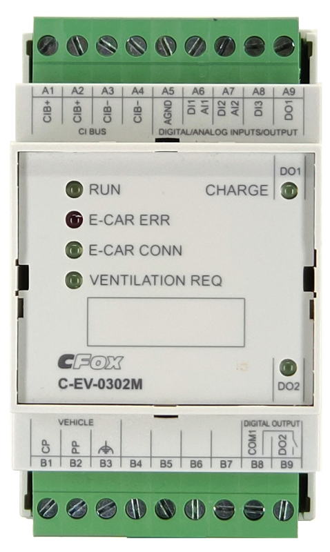
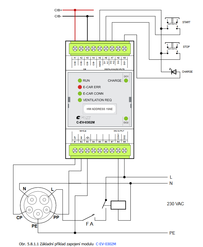
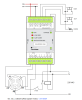
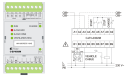
| Connection description | The power supply of the module is from the CIB bus. The CIB bus can have any topology and branching up to a distance of 500 m and up to 32 units on one CIB branch. The maximum consumption of all modules in one CIB branch is limited to 1A. The device contains a bus according to the IEC 61851-1 standard for controlling the AC charging of electric vehicles. DO1 is used to connect the charging indicator diode. The diode is connected to DO1 directly without resistance. This LED indicates that the electric car is charging. The E-CAR ERR LED indicates an error on the bus for charging electric cars, or a disconnected electric car during charging. The E-CAR CONN LED indicates the connection of the electric car. The VENTILATION REQ LED indicates the space ventilation request during charging. The CHARGE LED indicates that the electric car is charging. |
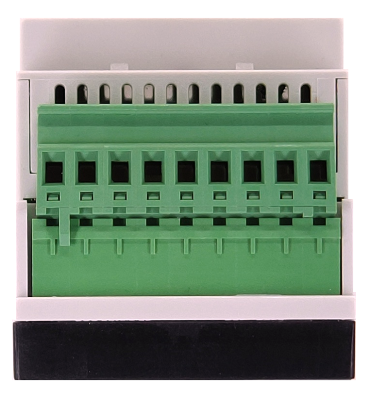
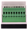
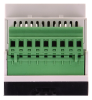
| Connection of power and system communication | connector with 2.5 mm2 screw terminal |
| Module operation | |
| Module configuration | The module is operated, set up and diagnosed from the Mosaic development environment. |
| Module diagnostics | The basic diagnostics is performed internally and the result is available in the relevant registers of the Mosaic environment. The module contains an indication LED for checking the status of inputs / outputs. By pressing the Manual Control button, the module can be switched to manual mode and the individual outputs can be controlled. |
| Maintenance | |
| Description | The module does not require any maintenance under general installation conditions. The operations in which a part of the module has to be dismantled must always be carried out with the supply voltage disconnected. |
| Notice | Because the module contains semiconductor components, it is necessary to follow the principles for working with electrostatic sensitive components when handling the removed cover. It is not allowed to directly touch the printed circuit boards without protective measures !!! |
| Warranty | |
| Generally | Warranty and complaint conditions are governed by the Terms and Conditions of Teco a.s. |
| Notice | You must meet all the conditions of this documentation before turning on the system. The system must not be put into service unless it has been verified and confirmed that the machinery meets the requirements of Directive 89/392 / EEC, in so far as it applies to it. Documentation subject to change. |
HW documentation
C-EV-0302M Basic documentation
199.81 kB, (CS, EN)
C-EV-0302M Basic documentation
1.00 MB, (EN)
User manuals
Peripheral module on CIB-Common Installation Bus(R) (cs), TXV00413_01
14.01 MB
Peripheral modules on the CIB Common Installation Bus(R) (en), TXV00413_02
13.94 MB, (EN, RU, DE, UA)
EC - Declaration of Conformity
Foxtrot - EC Declaration of conformity
295.20 kB, (EN, RU, DE, UA)
- Function block fbEVSEChargerAC and its use with C-EV-0302M - The function block enables operation and control of electric vehicle charging by AC module C-EV-0302M . This FB is based on the involvement in the following article . The unit can be operated in several charging modes. Automat...
- operation of the C-EV-0302M module - The EVSE_AC_lib library contains a function block for charging electric vehicles using the CIB module C-EV-0302M . EVSE_AC_lib is supported by all Foxtrot variants. The library does not require an application profile. The function block enab...
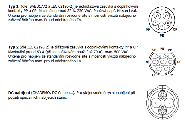
- C-EV-0302M - ...ignal is used by the car electronics as information about the connected charging cable; the signal is controlled by the C-EV-0302M module . The CP signal is used both to control the charging current in the range from about 5%...
- Control of 1f charging of an electric car by the C-EV-0302M module - ...he charging station for charging with alternating current from the 230V distribution network, single-phase design using the C-EV-0302M module. The example shows a 1f Type 1 charging connector (according to SAE J1772 and IEC 62196-2 ), which is...
- Power dissipation of modules for calculation of switchboard heating - ...3x AI, 8X DI, 1x AO, 8x RO, ext. power supply C-RM-1109M 4,0 W TXN 133 85 C-EV-0302M; EV charging control module EV C-EV-0302M 2,0 W TXN 133 92...
- Charging control for electric vehicles - ...also with the possibility of controlling charging priorities, etc. Using the Foxtrot system supplemented by the C-EV-0302M module, we can control the charging of one or more electric cars depending on the current operation of other elect...
- Connection of CP-1091 for efficient control of energy produced from PV and HFVE - ...ses, smaller companies, but also larger network installations with several 3-phase heaters and 3-phase PV. By adding eg a C-EV-0302M module an assembly is created which, in addition, can efficiently and effectively charge one or more electri...
- Electric car charging and supervision from Foxtrot - With the development of electromobility, more support for charging infrastructure is also required. Thanks to the C-EV-0302M module, connected to the CIB bus, it is possible to control and integrate the charging of electric vehicles up to 2...
No data available.