

C-EV-0505MTXN 143 13
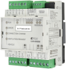
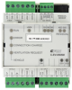
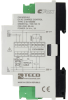
C-EV-0505M; Electric vehicle AC charging control module; PP, CP, 2x AI/DI, 1x DI (for S0), 1x AI (AC), 2x RO, 1x RGB data, 24 VDC, 1x RCM, 2x Lock
| DI | 1x DI (S0) 1x PP |
|---|---|
| DI/AI | 3x DI/AI |
| DO | 1x CP (DO/DI) 1x LOCK 2x RO 1x RGB |
| AI | |
| AO | |
| COM | 1x CIB slave 1x RGB data (< 30x WS2812) CP, PP 1x input for residual current monitor (according to IEC 62752, IEC 60364-7-722) |
| SENSOR |
| Picture | Variant | Variant description |
|---|---|---|

|
C-EV-0505M |
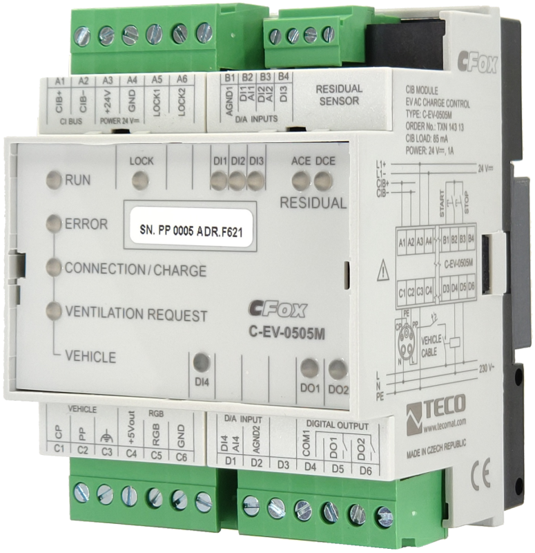
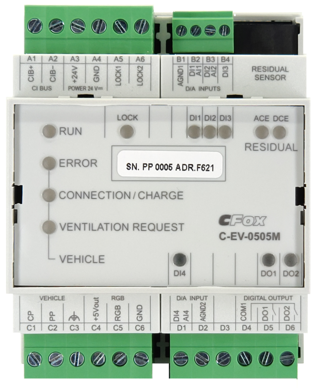
The C-EV-0505M module is intended for controlling the charging of electric cars with alternating current according to ČSN EN 61851-1. For charge control and back-diagnosis, the module contains CP (Control Pilot) and PP (Proximity function) outputs connected to the charging connector (Type 1, Type 2). In addition, the module contains relay outputs for controlling the contactor of the power supply to the electric car, one semiconductor output for controlling the charging connector lock, a data output for controlling up to 30 addressable RGB LED chips for charging signaling, a connector for connecting a residual AC/DC current monitor according to IEC 62752 and IEC 60364-7-772. The module also contains 3 universal AI/DI inputs and one counter input for counting pulses via the S0 interface from the supplied energy meter.
Enables the connection of an AC / DC leakage current control module (not included in the package).
The module has an input for a separate power supply from a 24 V DC source.
The module is designed for a DIN rail switchboard. It connects to the Foxtrot base module via the two-wire CIB Common Installation Bus®.
| Order num. | TXN 143 13 |
|---|---|
| Teco code | TXN 143 13 |
| Categories | CFox - Modules on DIN rail |
| Tags | - |
| COM - System buses | |
|---|---|
| CIB - Common Installation Bus (R): Installation I/O bus | 1x CIB slave |
| DI - Organization of binary inputs | |
| Total number of binary inputs | 4 |
| Number of groups of binary inputs | 2 |
| Organization of binary inputs into groups |
(AI1/DI1 - AI2/DI2, AI4/DI4) - group A, DI3 (S0) - group B, PP - group C |
| DI - Parameters of binary inputs DC (group A) | |
| Parameters valid for inputs on the terminals | AI1/DI1 - AI2/DI2, AI4/DI4, |
| Number of inputs in group | 3 |
| Common wire | AGND1 |
| Combined input type | DI / AI - measurement of resistance sensors, sensing of potential-free contacts and balanced loops |
| Galvanic separation of inputs from CIB bus | Yes |
| Pulse input overload capacity | max. 30 V (t < 10 ms) |
| Delay from log. 0 to log. 1 | 1 ms |
| Delay from log. 1 to log. 0 | 1 ms |
| Max. measuring voltage on the connected contact | 3,3 V DC |
| Internal input resistance | 2 kΩ |
| Max. resistance for closed contact, log. 1 | < 0,5 kΩ |
| Min. resistance for open contact, log. 0 | > 1,5 kΩ |
| Balanced resistance input | 1x <3,3 kΩ (tamper/0/1/tamper) |
| DI - Parameters of DC binary inputs (group B) | |
| Parameters valid for inputs on the terminals | DI3 |
| Number of inputs in group | 1 |
| Common wire | AGND - module ground |
| Combined input type | Binary, balanced and pulse counter according to the S0 standard |
| Galvanic separation of inputs from CIB | Yes |
| Max. measuring voltage on the connected contact | 15 V DC |
| Internal input resistance | 3,3 kΩ |
| Max. resistance for closed contact, log. 1 | < 0,8 kΩ |
| Min. resistance for open contact, log. 0 | > 4,2 kΩ |
| Balanced resistance input | 1x <3,3 kΩ (tamper/0/1/tamper) |
| DI - Parameters of binary inputs DC (group C) | |
| Parameters valid for inputs on the terminals | PP |
| Combined input type | Passive detection of maximum cable load according to ČSN EN 61851-1 ed. 2 |
| Notice | If the cable connection does not contain resistance Rc, it must be selected according to the table and connected directly between terminals B2 and B3 |
| Resistance connected to PP input for 13 A cable load | > 1,5 kΩ |
| Resistance connected to PP input for 20 A cable load | 680 Ω |
| Resistance connected to PP input for 32 A cable load | 220 Ω |
| Resistance connected to PP input for cable load 63 A 3f /70 A 1f | 100 Ω |
| DO/RO - Organization of binary outputs | |
| Total number of binary outputs | 4 |
| Number of binary output groups | 2 |
| Organization of binary outputs into groups |
1x CP: DO/DI 2x LOCK: DO - group A 1x RGB: DO - group B 2x RO |
| DO/DI - Output CP | |
| Parameters valid for outputs on terminals | CP |
| Output type | Control circuit according to ČSN EN 61851-1 ed. 2 |
| No load output voltage | ± 12 V |
| Rated frequency | 1 kHz |
| Output impedance | 1 kΩ |
| DO - Parameters of binary transistor outputs (group A) | |
| Parameters valid for the terminals | 2x (LOCK1, LOCK2) |
| Number of transistor outputs | 2 |
| Number of output groups | 1 |
| Number of outputs in group | 2 |
| Output type | semiconductor output, half-bridge (push-pull) |
| Galvanic isolation of the outputs from CIB | No |
| Nominal voltage of the lock drive | 24 V DC |
| Rated output current | 500 mA max. |
| DO - Parameters of binary transistor outputs (group B) | |
| Parameters valid for the terminals | RGB |
| Number of transistor outputs | 1 |
| Galvanic isolation of the outputs from CIB | Yes |
| Switching voltage | 5 V DC |
| Switching current, output load | 0,5A max. |
| Short circuit protection | Yes |
| RO - Parameters of binary relay outputs (group A) | |
| Parameters valid for the terminals | DO1, DO2 |
| Number of relay outputs | 2 |
| Number of output groups | 1 |
| Number of outputs in group | 2 |
| Output type | electromechanical relay, unprotected output |
| Contact type | NO - Normally Open |
| Galvanic separation from internal circuits | Yes |
| Diagnose | Alarm signaling on panel module |
| Switching current | 6 A max. for 250 V AC; 5 A max. for 30 V DC |
| Switching voltage | 400 V AC max., 30 V DC max. |
| Switching power | 1500 VA max for AC, 150 W max for DC |
| Short-term output overload - inrush | 15 A max. (10 ms max.) |
| Contact closing time | typ. 10 ms |
| Contact opening time | typ. 5ms |
| Mechanical life | min. 30,000,000 cycles |
| Short-circuit protection | No |
| Treatment of inductive load | External RC element, varistor (AC), diode (DC) |
| Insulation voltage between outputs and internal circuits | 3750 V AC |
| Insulation voltage between contacts | 1000 V AC |
| AI - Organization of analog inputs | |
| Total number of analog inputs | 3 |
| Number of analog input groups | 2 |
| Organization of analog inputs into groups | (AI1-AI2, AI4) - group A |
| Input type | AI / DI - combined |
| Common wire | AGND1 |
| AI - Analog Input Ranges (Group A) | |
| Parameters valid for inputs on the terminals | AI1/DI1 - AI2/DI2, AI4/DI4 |
| Passive sensor | Pt1000, W100 = 1,385 (-90 to +320 °C) |
| Passive sensor | Pt1000, W100 = 1,391 (-90 to +320 °C) |
| Passive sensor | Ni1000, W100 = 1,500 (–60 to +200 ° C) |
| Passive sensor | Ni1000, W100 = 1.617 (-60 to +200 ° C) |
| Passive sensor | Resistance transmitter 0-160 kOhm |
| Passive sensor | KTY81-121; PTC thermistor (-55 to + 125 °C) |
| Passive sensor | NTC Thermistor 12k / 25 °C (-40 to + 125 °C) |
| DI: Voltage-free contact | 0 when> 1.5 kOhm, 1 when <0.5 kOhm |
| DI: Balanced resistance input | 2x 1k1 (tamper/0/1/tamper) |
| Resistance measurement error - maximum error at 25 ° C | ± 2% of full scale |
| Residual current sensor parameters | |
| Frequency range | DC ÷ 2 kHz |
| Load current | <80 A RMS (single phase) or <3x 32 A RMS (three phase) |
| Measurement resolution | 0,2 mA |
| Residual current range | 0 ÷ 300 mA |
| Power supply | |
| Supply voltage, tolerances | 24 V DC, +25%, -15%, SELV |
| Power supply from CIB - voltage | 24/27 V DC |
| Auxiliary power supply - voltage | 24 V DC |
| Maximum power input | 2 W |
| Power supply from CIB - maximum current consumption (mA) | 85 mA |
| Galvanic separation of power supply from internal circuits | Yes |
| Internal protection | Yes |
| Size and weight | |
| Weight approx. | 150 g |
| Product dimensions (width x height x depth) | 70 х 90 х 58 mm |
| Module width in multiples of M (17.5 mm) | 4M |
| Operating conditions, product standards | |
| Product standard | ČSN EN 60730-1 ed. 2:2001 (mod IEC 60730-1:1999) |
| Product standard (B) | ČSN EN IEC 61851-1 ed. 3:2022 (idt IEC 61851-1:2017) |
| Protection class of electrical object | II, according to ČSN EN 61140 ed.3: 2016 (idt IEC 61140:2016) |
| IP rating (Ingress Protection) according to ČSN EN 60529: 1993 (idt IEC 529: 1989) | IP10B |
| Operating areas | Normal, acc. ČSN 33 2000-1 ed.2: 2009 (mod IEC 60354-1:2005) |
| Degree of pollution | 1, according to ČSN EN 60664-1 ed.2:2008 ( idt IEC 60664-1:2007) |
| Overvoltage category installation | II, according to EN 60664-1 ed_2: 2008 (idt IEC 60641-1: 2007) |
| Type of device | Module on DIN rail |
| Working position | Vertical |
| Type of operation (operating frequency) | Continuous |
| Ambient operating temperatures | –25 °C o +80 °C |
| Operating relative humidity | from 10 % up to 95 % without condensation |
| Operating atmospheric pressure | min. 70 kPa (<3,000 m above sea level) |
| Storage temperatures | –25 ° C to + 85 ° C |
| Electromagnetic compatibility, Mechanical endurance | |
| Electromagnetic compatibility / Emission | B, according to EN 55032 ed. 2: 2017 (idt CISPR 32: 2015) |
| Electromagnetic compatibility / Immunity | min. according to ČSN EN 60730-1 ed.2: 2001 |
| Sinusoidal vibration endurance | 10 Hz to 57 Hz, amplitude 0,075 mm, 57 Hz to 150 Hz, acceleration 1 G (Fc test according to EN 60068-2-6: 1997 (idt IEC 68-2-6: 1995), 10 cycles per axis.) |
| Packaginng, transportation, storage | |
| Description | The module is packed in a paper box. This documentation is also part of the package. The outer packaging is carried out according to the scope of the order and the method of transport in a transport package provided with labels and other data necessary for transport. The product must not be exposed to direct weather conditions during transport and storage. Malting of the product is only allowed in clean rooms without conductive dust, aggressive gases and vapors. The most suitable storage temperature is 20 ° C |
| Installation | |
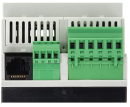
| Assembly description | The module is mounted in a vertical position on the U-rail ČSN EN 50022. Installation of the assembly (basic module and possibly peripheral modules) is performed according to TXV 004 13. |
| Attention! | The device may contain parts with dangerous voltages, covers being removed, or cabling manipulated, or disconnect the appropriate circuits or turn off the power !. |
| Connection | |
| Connection description |
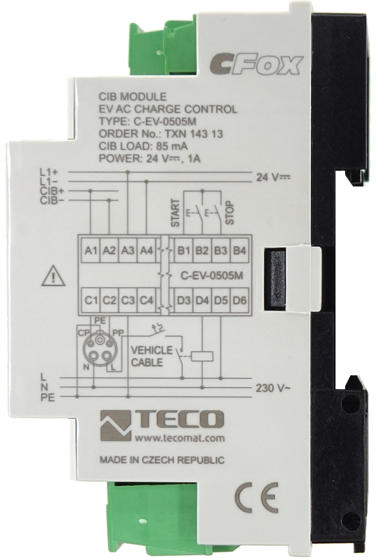
The module is powered by the CIB bus. The CIB bus can have any topology and branches up to a distance of 500 m and up to 32 units on one CIB branch. The maximum consumption of all modules of a single CIB branch is limited to 1A. The device contains a bus according to the IEC 61851-1 standard for controlling the AC charging of electric cars. DO1 is used to connect the charging indicator diode. The diode connects directly to DO1 without resistance. This LED indicates the charging of the electric car. The E-CAR ERR LED indicates an error on the bus for charging electric cars, or a disconnected electric car during charging. The E-CAR CONN LED indicates the connection of the electric car. The VENTILATION REQ LED indicates a request for room ventilation during charging. The CHARGE LED indicates charging of the electric car. If the residual current control module is used S-EV-0001X-RC (AC+DC) TXN 145 00 or S-EV-0002X-RDC (DC) TXN 145 01 (must be ordered separately), is connected using a non-crossed Ethernet cable into the RJ-45 connector. |
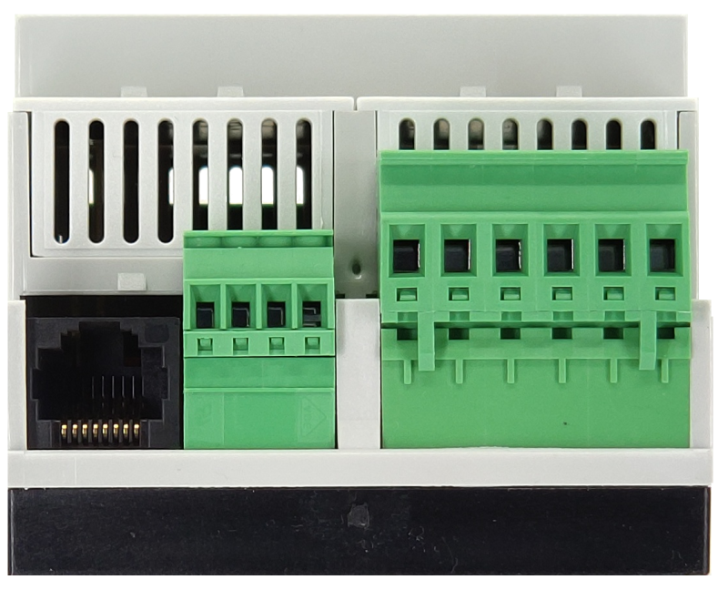
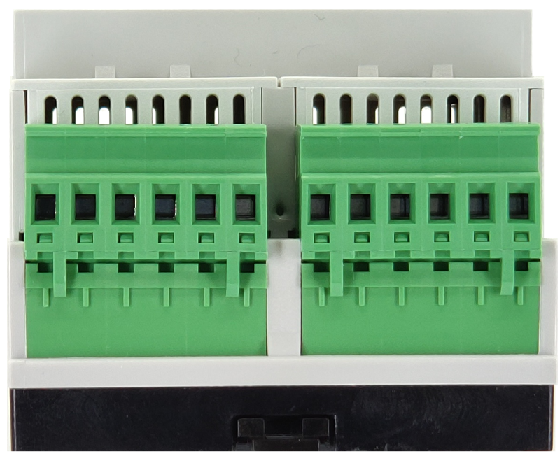
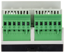
| Connection of power and system communication | connector with 2.5 mm2 screw terminal |
| Connection of inputs / outputs | connector with screw terminal 2.5 mm2 |
| Specific I / O | Residual current sensor S-EV-xxxx |
| Connection of specific I / O | RJ45 connector |
| CIB connection | connector with 2.5 mm2 screw terminal |
| Connection description | An example of module connection is shown in the following figure. |
| Module operation | |
| Commissioning | The module is operated, set and diagnosed from the MOSAIC programming environment or other parameterization software. The module is ready for operation after connecting the supply voltage and the CIB bus. The HW address is indicated on the label on the module. |
| Module diagnostics | The basic diagnostics is performed internally and the result is available in the relevant registers of the Mosaic environment. The module contains an indication LED for checking the status of inputs / outputs. By pressing the Manual Control button, the module can be switched to manual mode and the individual outputs can be controlled. |
| Maintenance | |
| Description | The module does not require any maintenance under general installation conditions. The operations in which a part of the module has to be dismantled must always be carried out with the supply voltage disconnected. |
| Notice | Because the module contains semiconductor components, it is necessary to follow the principles for working with electrostatic sensitive components when handling the removed cover. It is not allowed to directly touch the printed circuit boards without protective measures !!! |
| Warranty | |
| Generally | Warranty and complaint conditions are governed by the Terms and Conditions of Teco a.s. |
| Notice | You must meet all the conditions of this documentation before turning on the system. The system must not be put into service unless it has been verified and confirmed that the machinery meets the requirements of Directive 89/392 / EEC, in so far as it applies to it. Documentation subject to change. |
HW documentation
C-EV-0505M - Basic documentation
3.00 MB, (EN)
User manuals
Peripheral module on CIB-Common Installation Bus(R) (cs), TXV00413_01
14.01 MB
Peripheral modules on the CIB Common Installation Bus(R) (en), TXV00413_02
13.94 MB, (EN, RU, DE, UA)
Files for designers
Foxtrot 2 - library of elements in DXF and DWG formats, v. 2025/08.
21.80 MB
Foxtrot 2 - element library for SchemataCAD, v. 2025/08.
6.96 MB

S-EV-0001X-RC
TXN 145 00
S-EV-0001X-RC Residual current sensor 30 mA AC, 6 mA DC according to IEC 61851-22, IEC 62752

S-EV-0002X-RDC
TXN 145 01
S-EV-0002X-RDC Residual current sensor 6 mA DC in accordance with IEC 61851-22, IEC 62752
- Residual current submodule S-EV-0001X-RC for module C-EV-0505M - application note - ..., which significantly reduces installation costs. One measuring submodule S-EV-0001X-RC can be connected to the C-EV-0505M module. It is a submodule equipped with a residual (fault) current sensor type RCMB121-1. The sensor is sensitive...
No data available.