


SC-1101TXN 111 01
SC-1101; 1x RS-232/RS-485 interface
| DI | |
|---|---|
| DI/AI | |
| DO | |
| AI | |
| AO | |
| COM | 1x TCL2 slave 1x RS-232/RS-485 |
| SENSOR |
| Picture | Variant | Variant description |
|---|---|---|

|
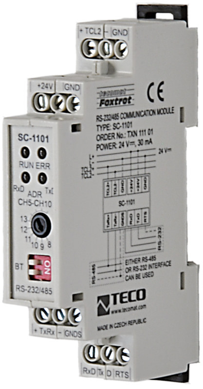
SC-1101 |
The SC-1101 module is a system communication module enabling the expansion of the central unit by another serial channel supporting UNI and PC modes.
A more detailed description of serial communications and their use is given in a separate manual Serial communication of TECOMAT programmable controllers - 32-bit model (order no. TXV 004 03.01).
Communication parameters are set in the Mosaic development environment within the project.
TECOMAT FOXTROT central units allow the connection of up to 6 system communication modules SC-1101 and SC-1102, which occupy channels CH5 - CH10. It should be borne in mind that due to the transmission capacity of the TCL2 bus, these serial channels are suitable for data- and time-consuming communications.
The SC-1101 module contains 1 serial channel with side-by-side RS-232 and RS-485 interfaces. Only one of these interfaces can be used at a time.
| Order num. | TXN 111 01 |
|---|---|
| Teco code | TXN 111 01 |
| Categories | Foxtrot - Communication Modules (TCL2) |
| Tags | - |
| COM - Serial channels | |
|---|---|
| Receiver input resistance (RS-232) | min. 7 kOhm |
| Signal output level (RS-232) | typ. ±8 V |
| Max. length of connected line (RS-232) | 15 m |
| Number of internal RS-485 serial channels | 1 |
| Receiver sensitivity (RS-485) | min. ±200 mV |
| Signal output level (RS-485) | typ. 3,7 V |
| Max. length of connected line (RS-485) | 1200 m |
| Note on cable length | The maximum length applies to twisted and shielded cable and communication speed max. 120 kBd. |
| COM - System buses | |
| TCL2 - system I/O bus | 1x TCL2 slave |
| Power supply | |
| Supply voltage, tolerances | 24 V DC, +25%, -15%, SELV |
| Maximum power input | 0,8 W |
| Module thermal/power loss | 0,8 W |
| Galvanic separation of power supply from internal circuits | Yes |
| Insulation voltage of galvanic separation | 1 000 VDC |
| Internal protection | Yes |
| Size and weight | |
| Weight approx. | 75 g |
| Product dimensions (width x height x depth) | 18 x 90 x 58 mm |
| Module width in multiples of M (17.5 mm) | 1M |
| Operating conditions, product standards | |
| Product standard | ČSN EN 60730-1 ed. 2:2001 (mod IEC 60730-1:1999) |
| Protection class of electrical object | I, according to ČSN EN 61140: 2003 (idt IEC 61140: 2001) |
| IP rating (Ingress Protection) according to ČSN EN 60529: 1993 (idt IEC 529: 1989) | IP10B |
| Operating areas | Normal, acc. ČSN 33 2000-1 ed.2: 2009 (mod IEC 60354-1:2005) |
| Degree of pollution | 1, according to ČSN EN 60664-1: 2004 (mod IEC 60664-1: 1992) |
| Overvoltage category installation | II, acc. ČSN EN 60664-1:2004 (mod IEC 606641:1992) |
| Type of device | Module on DIN rail |
| Working position | Any |
| Type of operation (operating frequency) | Continuous |
| Ambient operating temperatures | 0 ° C to + 70 ° C |
| Operating relative humidity | from 10 % up to 95 % without condensation |
| Operating atmospheric pressure | min. 70 kPa (<3,000 m above sea level) |
| Storage temperatures | –25 ° C to + 85 ° C |
| Packaginng, transportation, storage | |
| Description | The module is packed in a paper box. This documentation is also part of the package. The outer packaging is carried out according to the scope of the order and the method of transport in a transport package provided with labels and other data necessary for transport. The product must not be exposed to direct weather conditions during transport and storage. Malting of the product is only allowed in clean rooms without conductive dust, aggressive gases and vapors. The most suitable storage temperature is 20 ° C |
| Installation | |
| Assembly description | Module is mounted in a vertical position on the U-rail ČSN EN 50022. Assembly installation (basic module and possibly peripheral modules) is performed according to TXV 004 10.01. |
| Connection | |
| Connection of power and system communication | connector with 2.5 mm2 screw terminal |
| Power connection | wires 2.5 mm2 |
| Module installation tools | (+) PZ2, Pozidrivs screwdriver |
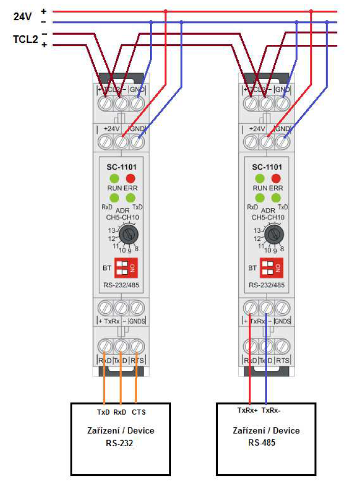
| Module connection | An example of module connection is shown in the following figure. The RS-485 line is terminated by switching both BT switches on the front panel of the module to the ON position (right). The RS-485 line must be terminated at each device located at each of the two ends of the line. If the device is connected in the middle of the line, termination is not performed. In this case, both BT switches will be to the left. |
| Module operation | |
| Commissioning | The module is operated as a system serial port, the settings are made in the Project Manager of the Mosaic programming environment, see the TXV 004 12 manual. |
| Module diagnostics | The basic diagnostic system of the module is a part of its standard software. It operates from module power on and operates independently of the user. Diagnostic error states of the module and connected peripheral modules of the assembly are signaled |
| Maintenance | |
| Description | The module does not require any maintenance under general installation conditions. The operations in which a part of the module has to be dismantled must always be carried out with the supply voltage disconnected. |
| Notice | Because the module contains semiconductor components, it is necessary to follow the principles for working with electrostatic sensitive components when handling the removed cover. It is not allowed to directly touch the printed circuit boards without protective measures !!! |
| Warranty | |
| Generally | Warranty and complaint conditions are governed by the Terms and Conditions of Teco a.s. |
| Notice | You must meet all the conditions of this documentation before turning on the system. The system must not be put into service unless it has been verified and confirmed that the machinery meets the requirements of Directive 89/392 / EEC, in so far as it applies to it. Documentation subject to change. |
HW documentation
SC-1101 - Basic documentation
1.07 MB, (EN)
Scheme
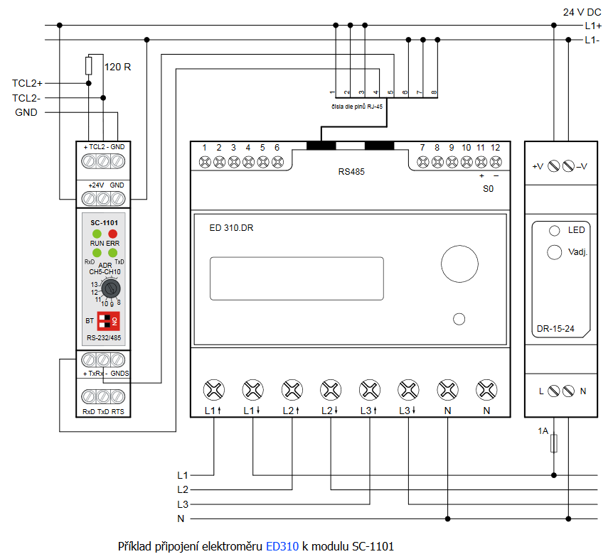
SC-1101 - Wiring diagram of ED310 electricity meter
62.67 kB
Files for designers
Foxtrot 2 - library of elements in DXF and DWG formats, v. 2025/08.
21.80 MB
Foxtrot 2 - element library for SchemataCAD, v. 2025/08.
6.96 MB
EC - Declaration of Conformity
Foxtrot - EC Declaration of conformity
295.20 kB, (EN, RU, DE, UA)
- SC-1101, an additional RS-232 and RS-485 interfaces - The SC-1101 is a system communication module for the extension of the central unit by another serial communication channel supporting the UNI and PC modes; it contains 1 serial port with parallel terminated interfaces RS-232 and RS-485 (only one of...
- Peripheral module address fixation on TCL2 - ...Typ verze hw verze firmwaru SC-1101 všechny verze 1.4 a vyšší...
- Power dissipation of modules for calculation of switchboard heating - ...6xDI, 1x DI/230VAC; 2xDI/230VAC,9xDO; 3xRO, 1xCIB CP-1091 7,0 W TXN 111 01 SC-1101 1x RS-232/RS-485 interface SC-1101 0,8 W TXN 111 02 SC-1102; 1x CAN...
- Communication interface CH2 ÷ CH4, using multiple submodules - ...(some basic modules have three) are not enough, it is possible to add several serial channels RS-232, RS-485 or CAN via the SC-1101 and SC-1102 external communication modules. Table.1: Interface combination for individual ch...
- SC-1102, an additional interface CAN module - ...odel (order No. TXV 004 03.01). The Foxtrot basic module allows the connection of up to 6 system communication modules SC-1101 and SC-1102, which occupy CH5 - CH10 channels. One should bear in mind that due to the transmission capacity of the T...
- Connecting the JABLOTRON 100 system - ...channel, e.g. the CH2 channel of the CP-1000 basic module (see the example below) or to an external communication module SC-1101 . The JA-121T module also requires an external supply voltage of 12 V DC, which can be provided either by an exter...
- CP-2000 and DMX - ...al unit which submodul card should be that work with DMX? The function block only work with CH3 and CH4. Can't the SC-1101 be good?...