
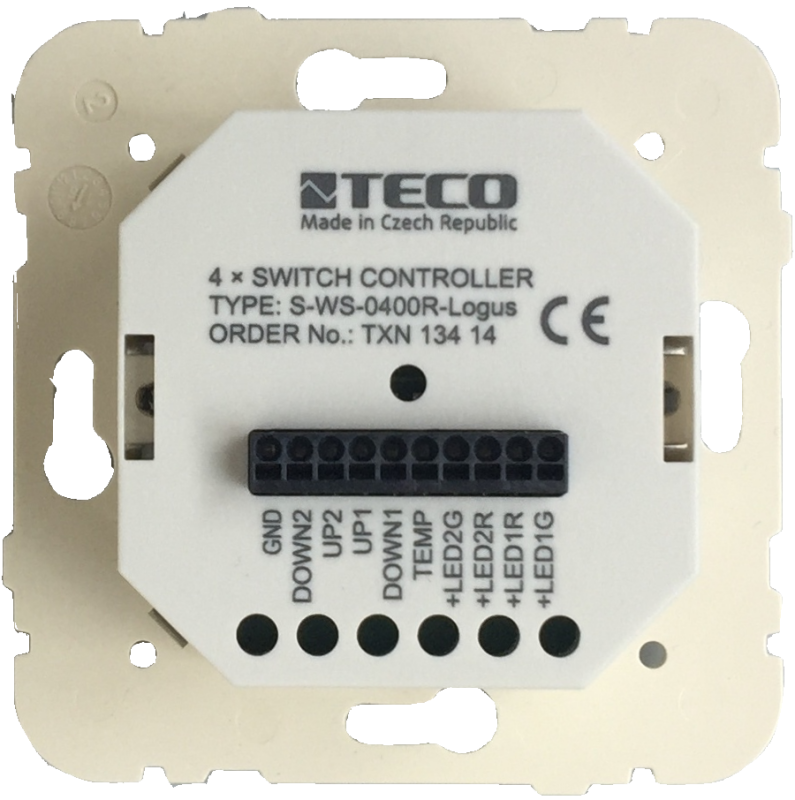
S-WS-0400R-LogusTXN 134 14
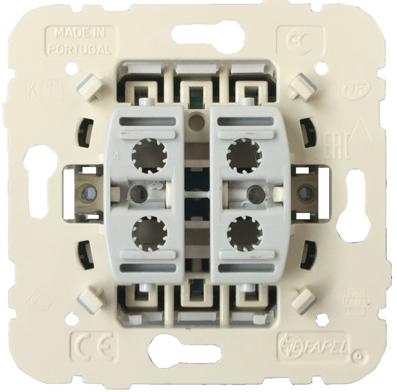
S-WS-0400R-Logus; 4x short stroke buttons/contacts 24V module for design Logus
| DI | |
|---|---|
| DI/AI | |
| DO | |
| AI | |
| AO | |
| COM | |
| SENSOR | 4x button 1x NTC 12K 2x green LED 2x LED red |
| Picture | Variant | Variant description |
|---|---|---|

|
S-WS-0400R-Logus |
S-WS-0400R-Logus; 4x short stroke buttons/contacts 24V module for design Logus
| Order num. | TXN 134 14 |
|---|---|
| Teco code | TXN 134 14 |
| Categories | CFox - LOGUS, Covers and devices |
| Tags | - |
| Parameter des Temperatursensors | |
|---|---|
| Temperature - Sensor type | NTC 12k |
| Contact parameters | |
| Maximum switching voltage | 27 V DC |
| LED indication parameters | |
| Maximum LED current | 25 mA |
| Size and weight | |
| Weight approx. | 70 g |
| Product dimensions (width x height x depth) | 86 × 86 × 38 mm |
| Operating conditions, product standards | |
| IP rating (Ingress Protection) according to ČSN EN 60529: 1993 (idt IEC 529: 1989) | IP10B |
| Operating areas | Normal, acc. ČSN 33 2000-1 ed.2: 2009 (mod IEC 60354-1:2005) |
| Degree of pollution | 1, according to ČSN EN 60664-1 ed.2:2008 ( idt IEC 60664-1:2007) |
| Overvoltage category installation | II, according to EN 60664-1 ed_2: 2008 (idt IEC 60641-1: 2007) |
| Type of device | In the installation box on the wall |
| Working position | Vertical |
| Type of operation (operating frequency) | Continuous |
| Ambient operating temperatures | 0 °C to + 55 °C |
| Operating relative humidity | from 10 % up to 95 % without condensation |
| Operating atmospheric pressure | min. 70 kPa (<3,000 m above sea level) |
| Storage temperatures | –25 °C to +70 °C |
| Installation | |
| Assembly description |
The module is mounted in a vertical position on a standard installation box with a spacing of fixing screws of 60 mm. Method: 1. screw the support plate to the installation box (pay attention to the position) 2. connect the wires to the connector 3. attach the frame to the installation box and snap the module into place 4. click the fingerboards |
| Connection | |
| Connection of inputs / outputs | terminal block with spring clamp 0.15-0.5 mm2, push-in |
| Module connection | The S-WS-0200R module is intended for connection to the module on the CIB bus C-IT-0504S (TXN 133 26) or C-IT-0908S (TXN 133 52). It can also be connected to other inputs and outputs while maintaining the polarity of the inputs and outputs. The LED outputs can also be switched by analog outputs, which supply 10 mA at 10 V. The configuration of inputs and outputs is performed in the superior module. |
| Maintenance | |
| Description | The module does not require any maintenance under general installation conditions. The operations in which a part of the module has to be dismantled must always be carried out with the supply voltage disconnected. |
| Warranty | |
| Generally | Warranty and complaint conditions are governed by the Terms and Conditions of Teco a.s. |
| Notice | You must meet all the conditions of this documentation before turning on the system. The system must not be put into service unless it has been verified and confirmed that the machinery meets the requirements of Directive 89/392 / EEC, in so far as it applies to it. Documentation subject to change. |
HW documentation
S-WS-0400R-Logus_ce.pdf - Basic documentation
155.46 kB
Files for designers
Foxtrot 2 - library of elements in DXF and DWG formats, v. 2025/08.
21.80 MB
Foxtrot 2 - element library for SchemataCAD, v. 2025/08.
6.96 MB
No data available.
No data available.