


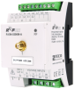
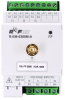


R-EM-0300M-A, 3f electricity meterTXN 142 09.A
R-EM-0300M-A; RFox2 fast electricity meter/quality meter, power supply 230 V AC/DC, 3x U, 3x I - for current transformer x:333 mV, radio type A
| DI | |
|---|---|
| DI/AI | |
| DO | |
| AI | 3x U, 3x I (3f, 230/400 V AC) |
| AO | |
| COM | 1x RFox2 Slave |
| SENSOR |
| Picture | Variant | Variant description |
|---|---|---|

|
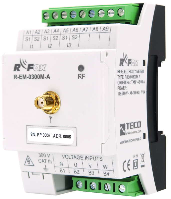
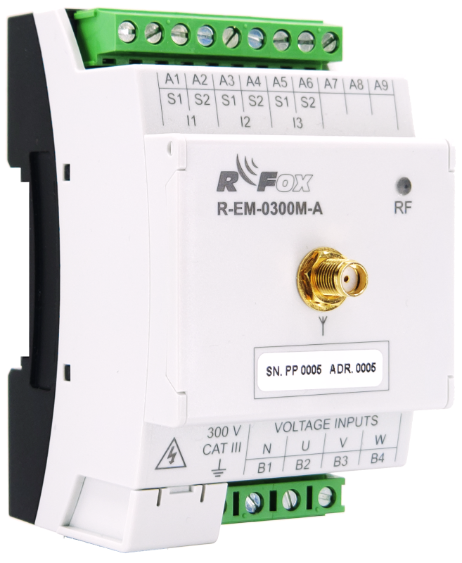
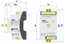
R-EM-0300M-A, 3f electricity meter |
Module of a 3-phase 4-quadrant fast electricity meter / quality meter providing all parameters of the consumed and supplied energy every 200 ms. The measurement is indirect, currents are sensed according to current transformers according to the required input range with a unified output of 333 mV. The data is transmitted wirelessly in the RFox2 radio network.
| Order num. | TXN 142 09.A |
|---|---|
| Teco code | TXN 142 09.A |
| Categories | RFox2 - DIN Rail Modules, Electricity meters |
| Tags | - |
| COM - Wireless network | |
|---|---|
| RFox2 wireless network | RFox2 Slave |
| Communication frequency band | 868,1 MHz |
| Transmission power | +14 dBm |
| Input sensitivity | –108 dBm |
| Modulation type | 2-GFSK |
| Communication speed | 50 kbps |
| Measurement of supply network parameters - frequency | |
| Nominal frequency | 50/60 Hz |
| Frequency range | 42 - 70 Hz |
| Frequency measurement accuracy | ±20 mHz |
| Measurement of supply network parameters - voltage | |
| Rated voltage UNOM (UDIN) | 180–250VAC |
| Crest factor in UNOM | 2 |
| Measuring range, phase voltage (UL-N) | 8÷355 V AC |
| Measuring range, combined voltage (UL-L) | 14 ÷ 615 V AC |
| Voltage measurement accuracy | ± 0.05% of value or ± 0.1% of range |
| Temperature drift | ± 0.03% of value; ± 0.01% of range / 10 ºC |
| Measurement category | 300V CAT III |
| Input impedance | min. 6,12 MΩ |
| Input consumption | max. 0,05 VA |
| Permanent overload (UL-N) | 1355 V AC |
| Peak overload, for 1 s (UL-N) | 2140 V AC |
| Accuracy of voltage asymmetry measurement | ± 0.5% |
| Measurement of supply network parameters - currents | |
| Method for measuring current | indirect via current transformer |
| Nominal current of transformer Inom | Inom A AC => 333 mV AC |
| Crest factor at Inom | 1,8 |
| Measuring range | 0,003÷1,2×Inom |
| Current measurement accuracy | ± 0.1% of value or ± 0.01% of range |
| Input impedance | 39 kΩ |
| Input consumption | max. 5 μVA |
| Permanent overload | 2×Inom, 666 mV AC |
| Peak overload, for 1 s, repetition period min. 300 s | 10x INOM |
| Measurement of supply network parameters - other quantities | |
| Active power, measuring range (PNOM = UNOM × INOM×cosφ); [W, V, A] | limited by measured voltage and current ranges |
| Reactive power, measuring range (QNOM = UNOM × INOM×sinφ); [VA, V, A] | limited by measured voltage and current ranges |
| Reference conditions (A) |
• ambient temperature tA = 23 ± 2 °C • U = 80–120% UNOM • I = 1–120% INOM • PF = 1 for active power and cosφ • PF = 0 for reactive power |
| Accuracy of active or reactive power (A) | ± 0.5% of value or ± 0.01% of Pnom |
| Measurement accuracy PF and cos φ (A) | ±0,01 |
| Reference conditions (B) |
• ambient temperature tA = 23 ± 2 °C • U = 80–120% UNOM • I = 1–120% INOM • PF ≥0,5 for active power and cosφ • PF ≤0,87 for reactive power |
| Accuracy of active or reactive power (B) | ± 1% or ± 0.01% PNOM |
| Measurement accuracy PF and cos φ (B) | ±0,01 |
| Temperature drift performance | ± 0.05% of value or ± 0.02% PNOM / 10 ° C |
| Energy, measuring range | limited by measured voltage and current ranges |
| Accuracy of active energy measurement | class 1 (according to EN 62053-21) |
| Accuracy of reactive energy measurement | class 2 (according to EN 62053-23) |
| Power supply | |
| Supply voltage, tolerances | 115-280 V AC, 115-380 V DC |
| Input voltage frequency | 50-60 Hz |
| Typical power input | 2 W |
| Typical reactive power input | 7 VA |
| Galvanic separation of power supply from internal circuits | No |
| Internal protection | No |
| Size and weight | |
| Weight approx. | 150 g |
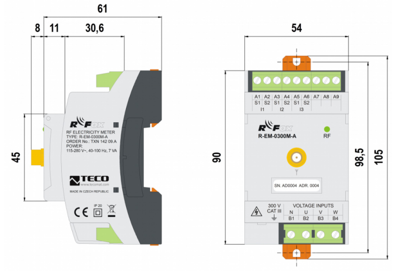
| Module width in multiples of M (17.5 mm) | 3M |
| Product dimensions (width x height x depth) | 54 × 90 × 69 mm |
| Operating conditions, product standards | |
| Product standard | ČSN EN 60730-1 ed.4 :2017 (EN 60730-1:2016) -Automatic electronic control device (for household and similar purposes) |
| Protection class of electrical object | II, according to ČSN EN 61140 ed.3: 2016 (idt IEC 61140:2016) |
| IP rating (Ingress Protection) according to ČSN EN 60529: 1993 (idt IEC 529: 1989) | IP20 |
| Operating areas | Normal, acc. ČSN 33 2000-1 ed.2: 2009 (mod IEC 60354-1:2005) |
| Degree of pollution | 2, according to ČSN EN 60664-1 ed.2: 2008 (idt IEC 60664-1: 2007) |
| Overvoltage category installation | III, according to EN 60664-1 ed_2: 2008 (idt IEC 60641-1: 2007) |
| Type of device | Module on DIN rail |
| Working position | Vertical |
| Type of operation (operating frequency) | Continuous |
| Ambient operating temperatures | -20 °C to + 55 °C |
| Operating relative humidity | from 10 % up to 95 % without condensation |
| Operating atmospheric pressure | min. 70 kPa (<3,000 m above sea level) |
| Storage temperatures | –25 °C to +70 °C |
| Electromagnetic compatibility, Mechanical endurance | |
| Electromagnetic compatibility / Emission | A, according to EN 55032 ed. 2: 2017 (idt CISPR 32: 2015) |
| Electromagnetic compatibility / Immunity | min. according to ČSN EN 60730-1 ed.3: 2012 |
| Sinusoidal vibration endurance | 10 Hz to 57 Hz, amplitude 0,075 mm, 57 Hz to 150 Hz, acceleration 1 G (Fc test according to EN 60068-2-6: 1997 (idt IEC 68-2-6: 1995), 10 cycles per axis.) |
| Packaginng, transportation, storage | |
| Description | The module with current transformers is packed in a paper box. This documentation is also part of the package. External packaging is carried out according to the scope of the order and the method of transport in a transport package provided with labels and other data necessary for transport. The product must not be exposed to direct weather conditions during transport and storage. The product may only be stored in clean rooms free of conductive dust, aggressive gases and vapors. The most suitable storage temperature is 20 °C. |
| Installation | |
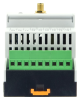
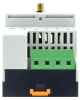
| Assembly description | The module can be mounted in two ways: either by mounting on the instrument support U rail 35 mm wide ČSN EN 60715, or by screwing three screws to the base (after extending the three fastening clips located at the bottom of the module, max. screw diameter is 4 mm). The dimensions of the module and the spacing of the holes for mounting the module on the screws are shown in Fig. 1. At the place of installation of the device and its immediate natural air circulation must be allowed in the surroundings. More information on installation can be found in the Design Guide CFox, RFox and Foxtrot, order no .: TXV 004 16. |
| Connection | |
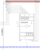
| Connection description |
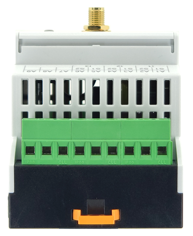
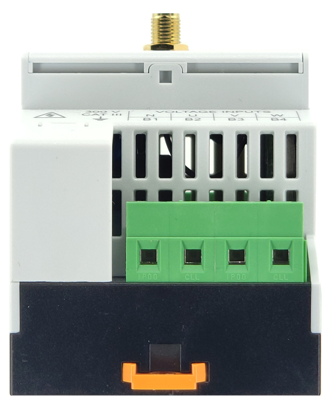
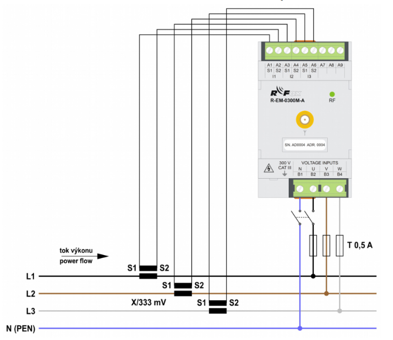
The module is connected with screw terminals. The measured voltages are connected to the terminals U, Va W via a suitable fuse element with characteristics according to the environment (eg fuse with a value of 0.5 A), the middle conductor is connected to the common terminal N. The module is powered via terminals U and N, therefore, it is necessary that the terminal N is always connected to a suitable potential (in a delta connection or in an Aaron connection). The voltage measuring inputs are connected to the internal circuits via a high impedance. To connect the current inputs, it is necessary to use measuring current transformers with a secondary winding with a nominal value of 333 mVs corresponding to the measurement category / insulation voltage or to install the transformers on an insulated primary conductor with a corresponding insulation voltage. The secondary windings of the transformers are connected to terminals S1 and S2 of the current inputs I1, I2 and I3. All terminals S2 are galvanically connected to the same potential inside the module. If it is necessary to ground the secondary side of the measuring transformers, it is therefore necessary to connect terminals S2. The recommended conductor type for connecting the measured voltage and current is H07V – U (CY) cross section 0.5 mm2–2.5mm2. The CIB bus is connected to the CIB + and CIB– terminals. The number of modules on the CIB bus is limited by the maximum permitted bus current. The correct connection of the module, including the correct connection of current transformers, is illustrated in Fig. 2 |
| Warnings / Cautions | The current inputs can never be used for direct current measurement! Using and connecting the wrong current transformer can seriously damage the module! |
| Connection of power and system communication | connector with 2.5 mm2 screw terminal |
| Connection of inputs / outputs | connector with screw terminal 2.5 mm2 |
| Module operation | |
| Module configuration | odul je po připojení pomocného napájecího napětí a sběrnice CIB připraven k činnosti. Neobsahuje žádné ovládací prvky a je obsluhován, nastavován a diagnostikován z programovacího prostředí MOSAIC. HW adresa je uvedena na štítku na předním panelu. Modul musí být obsluhován osobou s předepsanou kvalifikací pro takovou činnost a tato osoba se musí podrobně seznámit se zásadami práce s modulem. Pokud je modul připojen k částem, které jsou pod nebezpečným napětím, je nutné dodržovat všechna nezbytná opatření k ochraně uživatelů a zařízená před úrazem elektrickým proudem. Pracovník provádějící instalaci a/nebo údržbu zařízení musí být vybaven a při práci používat osobní ochranné pomůcky a další bezpečnostní prostředky. Je-li modul používán způsobem, který není specifikován výrobcem, může být ochrana poskytovaná modulem snížena. Další informace lze nalézt v příručce Periferní moduly na sběrnici CIB, obj. č.: TXV 004 13.01. |
| Commissioning |
The module is ready for operation after connecting the supply voltage. It does not contain any controls and is operated, set up and diagnosed from the MOSAIC programming environment. The HW address is indicated on the label on the front panel. When initializing the module, the correct value of the primary current INOM of the respective current transformers (current range) must be entered. Attention: When working with the module, it is necessary to observe all necessary measures to protect people and property from injury and damage by electric shock! The module must be operated by a person with the prescribed qualification for such an activity and this person must be thoroughly acquainted with the principles of working with the module. If the module is connected to parts that are under dangerous voltage, all necessary measures must be taken to protect users and equipment from electric shock. Workers installing and / or maintaining the equipment must be equipped with and use personal protective equipment and other safety equipment at work. If the module is used in a manner not specified by the manufacturer, the protection provided by the module may be reduced. |
| Module diagnostics | The basic diagnostics are performed internally and the measurement results are available in the relevant registers of the Mosaic environment. The status of the module is indicated by an LED on the front panel. When the supply voltage is connected, the diode lights up and its light also indicates the presence of power supply. After communication is established, the module is ready for operation. |
| Maintenance | |
| Instructions |
The module does not require any maintenance if the general conditions for installation are observed. The operations that require the module to be assembled or disassembled are always performed with the auxiliary power supply disconnected and the measuring inputs disconnected. Because the module contains semiconductor components, it is necessary to follow the principles for working with electrostatic sensitive components when handling the removed cover. It is not allowed to directly touch the printed circuit boards without protective measures. |
| Warranty | |
| Generally | Warranty and complaint conditions are governed by the Terms and Conditions of Teco a.s. |
| Notice | You must meet all the conditions of this documentation before turning on the system. The system must not be put into service unless it has been verified and confirmed that the machinery meets the requirements of Directive 89/392 / EEC, in so far as it applies to it. Documentation subject to change. |
HW documentation
R-EM-0300M-A - Basic documentation
812.56 kB, (CS, EN)
Files for designers
R-EM-0300M - Technical drawing M01 DWG
431.37 kB
R-EM-0300M - Technical drawing M01 DXF
1.73 MB
Foxtrot 2 - library of elements in DXF and DWG formats, v. 2025/08.
21.80 MB
Foxtrot 2 - element library for SchemataCAD, v. 2025/08.
6.96 MB
EC - Declaration of Conformity
Foxtrot 2 - EC Declaration of conformity (en)
590.59 kB, (EN, RU, DE, UA)
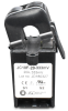
JC10F-333 20A
JC10F-333 20A
JC10F-333 20A, Current transformer with split core 20A / 333 mV, hole 10 mm
- C-EM-0300M (R-EM-0300M-A) - measurement of production and consumption of el. energy, 3f fast - ...ion to the control system, it is available in a version with a CIB bus ( C-EM-0300M ) or an RFox2 wireless connection ( R-EM-0300M-A ). The device measures three voltages and three currents. four-quadrant power measurement and electricit...
- Power dissipation of modules for calculation of switchboard heating - ...r motor control - 2 channels, 8x 24 V output C-OS-0808M 5,0 W TXN 142 09.A R-EM-0300M-A (radio 3-phase electricity meter KMB, 230 V, 3x measurement input U and I) R-EM-0300M-A 3,0 W...
- Antennas for RFox2 in version A, 868 MHz - ...na suitable for RFox2 modules equipped with an SMA connector for connecting an external antenna (eg modules C-RF-0001M-A , R-EM-0300M-A and others). Standards ZigBee, ISM, SIGFOX, LoRa Freque...
- Openable transformer for current measurement with 333 mV output - Current transformers with a secondary output voltage of 333 mV use, for example, electricity meters C-EM-0300M and R-EM-0300M-A . It is not necessary to short-circuit this transformer during handling. The split core of the current transforme...
- Metering electrical energy - ...We are currently preparing a simpler version of the CIB three-phase electricity meter C-EM-0300M and its wireless version R-EM-0300M-A. We have solutions with EMU and EMI modules for measuring consumption (and production) and other quantiti...
No data available.