

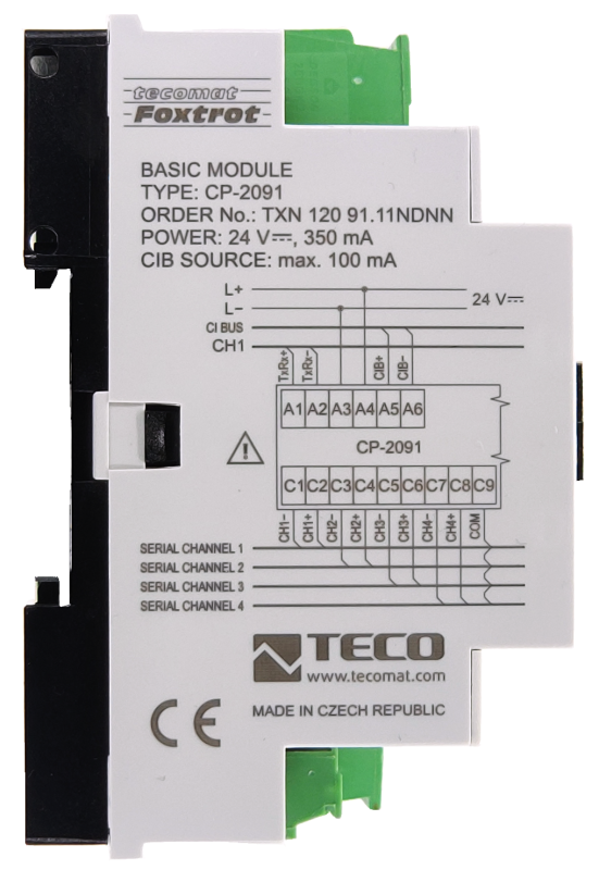

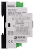

CP-2091.11NDNNTXN 120 91.11NDNN
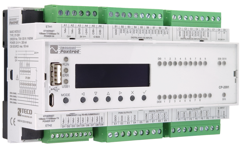
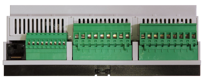
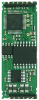
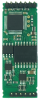
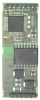
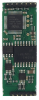
CP-2091; CPU, 2xETH100/10, 128kB dbox, LCD, 1x RS-485, 1xCIB, CH1-4, 8xAI/DI, 2xAI/DI/AO, 1x DI(230VAC), 2xAO/DO (PWM), 3xDO (PWM), 6xRO, 24VDC/230VAC
| DI | 6x DI/AI (HSC) 2x DI/AI/AO 1x DI (230 V AC) |
|---|---|
| DI/AI | 6x DI/AI |
| DO | 6x RO 3x DO (PWM) 2x DO/AO (PWM) |
| AI | |
| AO | 2x DO/AO 2x DI/AI/AO |
| COM | 2x ETH 4x CH1-4, slot for 2x submodule 1x RS-485 master 1x USB device 1x USB host 1x CIB master |
| SENSOR |
| Picture | Variant | Variant description |
|---|---|---|

|
CP-2091.11NDNN | Databox: 128 kB Processor: 1 core, ARMv7 792 MHz Display: OLED display large 55 x 13 mm |
Basic modules CP-2091 are from the assortment of basic modules (ZM) of modular programmable automata of the Foxtrot 2 series.
Basic modules CP-2091,
- 8x multi-purpose inputs, each of which can be used either as an analog input or as a binary potential-free contact,
- 2x multi-purpose binary outputs (24V DC) / analog outputs (0-10V)
- one binary input 230 V AC,
- 3x binary outputs 24 V 0.5 A with optional PWM function
- 3x separate relay outputs 230 V AC/5A.
- 3x separate relay outputs 230 V AC/16A
The following interfaces are also available:
2x Ethernet,
up to 4x serial channels
1x master CIB installation bus for connecting external peripherals
2x master system buses TCL2 (SE-0140) intended for connecting expansion I/O modules that increase the total number of I/O
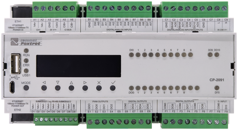
The CP-2091 basic module contains a basic LCD display with 4 x 20 characters and 6 user buttons.
Basic modules CP-2091,
- 8x multi-purpose inputs, each of which can be used either as an analog input or as a binary potential-free contact,
- 2x multi-purpose binary outputs (24V DC) / analog outputs (0-10V)
- one binary input 230 V AC,
- 3x binary outputs 24 V 0.5 A with optional PWM function
- 3x separate relay outputs 230 V AC/5A.
- 3x separate relay outputs 230 V AC/16A
The following interfaces are also available:
2x Ethernet,
up to 4x serial channels
1x master CIB installation bus for connecting external peripherals
2x master system buses TCL2 (SE-0140) intended for connecting expansion I/O modules that increase the total number of I/O
The CP-2091 basic module contains a basic LCD display with 4 x 20 characters and 6 user buttons.
| Order num. | TXN 120 91.11NDNN |
|---|---|
| Teco code | TXN 120 91.11NDNN |
| Categories | Foxtrot 2 - Basic modules |
| Tags | - |
| System parameters of the central unit | |
|---|---|
| Row of central unit | I |
| User program memory | 1 MB |
| Memory for user variables / including RETAIN variables | 320 kB/48 kB |
| Instruction length | 4 Byte |
| Backup of program source code in PLC | Yes, optional in Mosaic |
| On-line program change in PLC | Yes, including I / O configuration change |
| DataBox - additional internal data memory | 128/257 kB, optional |
| Memory for I / O data | 64 KB / 64 KB |
| File system - Internal Drive in PLC | 128 MB, journaling file system |
| File system - RAM disk PLC | 16 MB |
| File System - USB Flash Drive | Supported |
| File system - Micro SD card | supported (except for variants with WLAN1) |
| Optional memory card slot | microSD - Card Slot (<= 1TB) |
| Cycle time per 1k of logic instructions | 0,036 ms |
| Cycle time for 1k integer operations | 0,044 ms |
| Cycle time for 1k floating point operations | 0,043 ms |
| Development environment | Mosaic v2018.2 or higher |
| Programming languages | ST, IL, LD, FBD, SFC, CFC |
| RTC - Real time circuit | Yes |
| RTC - Backup time | typ. 500 hours |
| Integrated Web server | Yes |
| Integrated Datalogger | Yes |
| Access to PLC variables via web API | Yes |
| COM - Communication - IP/Ethernet | |
| Ethernet 10/100 Mb (ETHx) | 2 |
| WLAN2 (external via USB host, optional) | 1 |
| LTE interface (LTEx, optional) | 1 |
| Available system modes on ETH and WLAN |
UNI data exchange via UDP, TCP and SSL / TLS encryption support; PC EPSNET UDP / EPSNET TCP; PLC data sharing between PLCs (including CP-1xxx and CP-7xxx); PLD data sharing between PLC CP-2xxx and CP-8xxx including encryption |
| Available system modes on LTE |
UNI data exchange via UDP, TCP and SSL / TLS encryption support; EPSNET UDP / EPSNET TCP |
| TCP / IP protocol | Yes |
| UDP protocol | Yes |
| HTTPS protocol | Yes |
| HTTP protocol | Yes |
| WebSocket protocol | Yes |
| Protocol MODBUS/TCP | Yes |
| SMTP protocol | Yes |
| IEC 60870-5-104 protocol | Yes |
| REST API | Yes |
| COM - USB | |
| USB devices interface | 1x micro-USB |
| USB host interface | 1x USB-A |
| Available system modes on USB | PC |
| COM - Serial channels | |
| max. number of serial channels that can be serviced at one time | 10 |
| max. number of internal serial channels | 1 |
| max. number of optional serial channels in the basic module | 4 |
| number of slots for optional submodules with interface (MR-013x) | 2 |
| max. number of expanding serial channels on the TCL2 bus | 6 times on each TCL2 line |
| COM - Internal serial channels | |
| Number of internal serial channels | 1x RS-485 |
| Available system modes on the internal serial channel |
UNI general channel with any asynchronous communication PC communication with superior systems via EPSNET protocol MAS communication with EPSNET subordinate systems |
| Available communication speeds of system modes | 1200 Bd, 2400 Bd, 4800 Bd, 9600 Bd, 14 400 Bd, 19 200 Bd, 28 800 Bd, 38 400 Bd, 57 600 Bd, 76 800 Bd, 115 200 Bd, 172 800 Bd, 230 400 Bd, 345 600 Bd |
| Galvanic separation of the internal serial channel | No |
| Receiver sensitivity | min. ±200 mV |
| Signal output level | typ. 3 V |
| Max. length of connected line | 1200 m |
| Note on cable length | The maximum length applies to twisted and shielded cable and communication speed max. 120 kBd. |
| COM - Submodules with serial channels and optional interface | |
| Number of slots for submodules with optional interface (MR-013x) | 2 |
| RS-232 serial channel on submodules | 1x on MR-0130, 2x on MR-0134 |
| Available communication speeds of modes on the RS-232 interface | 1200 Bd, 2400 Bd, 4800 Bd, 9600 Bd, 14 400 Bd, 19 200 Bd, 28 800 Bd, 38 400 Bd, 57 600 Bd, 76 800 Bd, 115 200 Bd, 172 800 Bd |
| RS-485 serial channel on submodules | 1x on MR-0131, 2x on MR-0133 |
| Available communication speeds of modes on the RS-485 interface | 1200 Bd, 2400 Bd, 4800 Bd, 9600 Bd, 14 400 Bd, 19 200 Bd, 28 800 Bd, 38 400 Bd, 57 600 Bd, 76 800 Bd, 115 200 Bd, 172 800 Bd, 230 400 Bd, 345 600 Bd |
| Available system modes on submodules MR-0130..MR-0134 | UNI, PC, MAS |
| Profibus DP serial channel on submodules | 1x on MR-0135 |
| Available communication speeds of the PFB system mode | 9600 Bd, 19 200 Bd, 93 750 Bd, 187 500 Bd |
| Profibus DP master protocol (<180 kbit/s) | PFB - Profibus DP Master (<180 kbit / s) |
| COM - Expansion communication modules on the TCL2 bus | |
| RS-232 serial channel on modules | 1x on SC-1101 (either RS-232 or RS-485) |
| RS-485 serial channel on modules | 1x on SC-1101 (either RS-485 or RS-232) |
| Wireless M-Bus wireless communication channel on modules | 1x on SC-1112.T |
| RFox2 wireless communication channel on modules | 1x on SC-1111 |
| Available communication modes on modules SC-1101, SC-1111, SC-1112 | UNI - universal |
| Modbus RTU / ASCII master / slave protocol available on mode modules | UNI - Universal |
| CAN serial channel on modules | 1x on SC-1102 |
| Available communication modes on SC-1102 modules | CSJ - CAN bus connection |
| OpenTherm communication channel on modules | 1x on UC-12044 |
| MP-Bus communication channel on the modules | 1x on UC-1203 |
| COM - Expansion communication modules on the CIB bus - Common Installation Bus (R) | |
| RFox2 wireless communication channel on modules | 1x to C-RF-0001M-A; 1x RFox2 master, max. 10 addresses |
| DALI Communication interface on modules | 1x and C-DL-0064M; 1x Master for 64 addresses |
| Wiegand communication interface on modules | 1x on C-WG-0503S; 1x Master, formats 42 bits, 34bits, 26 bits, 40bits transparent |
| COM - System buses | |
| CIB - Common Installation Bus (R): Installation I/O bus | 1x CIB master (100 mA) |
| CIB - Address range of one branch of the installation bus | 32 CFox I/O modules |
| ITCL - internal system bus | Yes |
| ITCL - number of exchangeable submodules | 2 |
| ETCL - external system bus | 1 (ETH1 or ETH2) |
| DI - Organization of binary inputs | |
| Total number of binary inputs | 11 |
| Number of groups of binary inputs | 2 |
| Organization of binary inputs into groups |
4x DI/AI (DI0/AI0-DI7/AI7) 6x DI/AI (HSC) (DI0/AI0-DI5/AI5) 2x DI/AI/AO (DI8/AI8/AO0-DI9/AI9/AO1) 1x DI 230 V AC (DI10) |
| DI - Parameters of binary inputs DC (group A) | |
| Parameters valid for inputs on the terminals | DI0-DI9 |
| Number of inputs in group | 10 |
| Common wire | minus |
| Input type | active (for dry contacts connection) |
| Combined input type | DI/AI Active, for sensing potential-free contacts and measuring resistance sensors |
| Galvanic isolation of inputs from internal/peripheral circuits | No |
| Diagnostics | indication of energized input by LED on module panel |
| Pulse input overload capacity | max. 30 V (t < 10 ms) |
| Input voltage for log. 0 | +3 V DC min. |
| Input voltage for log. 1 | 1 V DC max. |
| Input current at log. 1 (typ.) | -1 mA |
| Delay from log. 0 to log. 1 | 500 μs |
| Delay from log. 1 to log. 0 | 500 μs |
| The minimum width of the captured pulse | 500 μs |
| DI - Parameters of binary AC inputs | |
| Parameters valid for AC inputs on the terminals | DI10 |
| Total number of binary AC inputs | 1 |
| Number of groups of AC inputs | 1 |
| Number of AC inputs in group | 1 |
| Organization of binary inputs into groups | 1x DI (DI10) |
| Diagnostics | Alarm of excited input on the panel |
| Input type | conventional switch |
| Galvanic isolation of internal circuits | Yes |
| Insulation voltage | 3750 V AC |
| Input voltage for log. 0 | 0 v AC min., 50 V AC max. |
| Input voltage for log. 1 | 230 V AC typ. 95 V AC min., 260 V AC max. |
| Input current at log. 1 (typ.) | 5 mA typ. |
| Delay from log. 0 to log. 1 | max. 20 ms |
| Delay from log. 1 to log. 0 | max. 20 ms |
| HSC - Counter input parameters | |
| The parameters are valid for inputs | DI0-DI5 |
| Special input functions | one-way counter |
| Counter: Input frequency / resolution | 1 kHz |
| Pulse width | min. 500 μs |
| Delay from log. 0 per log. 1 | 500 μs |
| Delay from log. 1 per log. 0 | 500 μs |
| Range of registers | up to 32 bits, 0 to 4 294 967 296 |
| HSC - PWM input parameters | |
| Frequency range | 10 Hz - 1 kHz |
| PWM input error | <1% (at 1 kHz) |
| Input resolution | 10,4 μs (DI0), 0,2 μs (DI1) |
| DO/RO - Organization of binary outputs | |
| Total number of binary outputs | 11 |
| Number of binary output groups | 4 |
| Organization of binary outputs into groups |
6x RO (DO3-DO5, DO6-DO8 3x DO (PWM) (DO0-DO2) 2x DO/AO (DO9/AO2 - DO10/AO3) |
| DO - Parameters of binary transistor outputs (group A) | |
| Parameters valid for the terminals | DO0-DO2, DO9-DO10 |
| Number of transistor outputs | 5 |
| Number of output groups | 2 |
| Number of outputs in group | 5 |
| Organization of transistor outputs into groups | 3x DO (DO0-DO2) + 2x DO (DO9-DO10) |
| Common group conductor | minus |
| Output type | MOSFET (Low-side switch) |
| Galvanic separation from internal circuits | No |
| Diagnostics | indication of energized output by LED on module panel |
| Switching voltage | 5 - 30 V DC |
| Switching current, output load | 0,5 A max. |
| Short-term output overload capacity | 3 A max. |
| Output resistance | typ. 0,16 Ω, max. 0,4 Ω |
| Switching time | typ. 9 μs |
| Opening time | typ. 13 μs |
| Internal protection | overvoltage, short circuit and overheating protection |
| RO - Parameters of binary relay outputs (group A) | |
| Parameters valid for the terminals | DO3-DO5 |
| Number of relay outputs | 3 |
| Number of output groups | 1 |
| Number of outputs in group | 3 |
| Organization of relay outputs into groups | 3x RO (DO3-DO5) |
| Output type | electromechanical relay, unprotected output |
| Contact type | NO - Normally Open |
| Galvanic separation from internal circuits | Yes |
| Diagnose | Alarm signaling on panel module |
| Switching current | 3 A max., 100 mA min. |
| Switching voltage | 250 V AC max., 5 V AC min., 30V DC max. |
| Switching power | 1250 VA max. for AC, 90 W max. for DC |
| Short-term output overload - inrush | 4 A max. |
| Current through common clamp | 10 A max. |
| Contact closing time | typ. 10 ms |
| Contact opening time | typ. 4 ms |
| Limit values of switched resistive load | max. 3A at 30 V DC or 230 V AC |
| Switching inductive load limits DC13 | max. 3 A at 30 V DC |
| Switching inductive load limits AC15 | max. 3 A at 230 V AC |
| Switching frequency without load | max. 300 switching / min. |
| Switching frequency with rated load | max. 20 switching / min. |
| Mechanical life | min. 5,000,000 cycles |
| Electrical life at maximum resistive load | min. 100,000 cycles |
| Electrical life at maximum load inductive DC13 | min. 100,000 cycles |
| Electrical life at maximum load inductive AC15 | min. 100,000 cycles |
| Short-circuit protection | No |
| Treatment of inductive load | External RC element, varistor (AC), diode (DC) |
| Insulation voltage between outputs and internal circuits | 3750 V AC |
| Isolation voltage between groups of outputs to each other | 3750 V AC |
| RO - Parameters of binary relay outputs (group B) | |
| Parameters valid for the terminals | DO6-DO8 |
| Number of relay outputs | 3 |
| Number of output groups | 3 |
| Number of outputs in group | 1 |
| Organization of relay outputs into groups | 1x RO (DO6) + 1x RO (DO7) +1x RO (DO8) |
| Output type | electromechanical relay, unprotected output |
| Contact type | NO - Normally Open |
| Galvanic separation from internal circuits | Yes |
| Galvanic isolation between groups | Yes |
| Diagnose | Alarm signaling on panel module |
| Switching current | 10 A max., 100 mA min. |
| Switching voltage | max. 250 V AC; max. 30 V DC; min. 5 V |
| Short-circuit protection | No |
| Short-term output overload | 10A max. |
| Current through common clamp | 10 A max. |
| Contact closing time | typ. 10 ms |
| Contact opening time | typ. 4 ms |
| Limit values of switched resistive load | max. 10A at 30 V DC or 230 V AC |
| Switching inductive load limits DC13 | max. 10 A at 30 V |
| Switching inductive load limits AC15 | max. 10 A at 230 V AC |
| Switching frequency without load | max. 300 switching / min. |
| Switching frequency with rated load | max. 6 switching / min |
| Mechanical life | min. 5,000,000 cycles |
| Electrical life at maximum resistive load | min. 100,000 cycles |
| Electrical life at maximum load inductive DC13 | min. 100,000 cycles |
| Electrical life at maximum load inductive AC15 | min. 100,000 cycles |
| Treatment of inductive load | External RC element, varistor (AC), diode (DC) |
| Insulation voltage between outputs and internal circuits | 3750 V AC |
| Isolation voltage between groups of outputs to each other | 3750 V AC |
| AI - Organization of analog inputs | |
| Total number of analog inputs | 10 |
| Number of inputs per group | 10 |
| Number of analog input groups | 1 |
| Organization of analog inputs into groups | 10 (DI0/AI0-DI9/AI9) |
| Input type | With common clamp |
| Common wire | Minus |
| Galvanic separation from internal circuits | No |
| Diagnostics | overload signaling in status word |
| External power supply | No |
| Digital resolution | 12 bit |
| Converter type | Approximation |
| conversion time | 20 μs |
| Operating modes | periodic input sensing |
| Filtration | low pass filter, digital comb filter 50/60 Hz |
| Insulation potential | 500 V DC between input and internal circuits |
| AI - Analog Input Ranges (Group A) | |
| Parameters valid for inputs on the terminals | DI0/AI0 - DI9/AI9 |
| Passive sensor | Pt1000, W100 = 1,385 (-90 to +400 °C) |
| Passive sensor | Pt1000, W100 = 1,391 (-90 to +400 °C) |
| Passive sensor | Ni1000, W100 = 1,500 (–60 to +200 ° C) |
| Passive sensor | Ni1000, W100 = 1.617 (-60 to +200 ° C) |
| Passive sensor | Resistance transmitter 0-2 kOhm |
| Passive sensor | KTY81-121; PTC thermistor (-55 to + 125 °C) |
| Input impedance in signal range RTD | > 4 kΩ |
| Resistance measurement error - maximum error at 25 ° C | ± 0.5% of full scale |
| Resistance measurement error - temperature coefficient | ± 0.05% of full scale / K |
| Resistance measurement error - non-linearity | ± 0.09% of full scale |
| Resistance measurement error - repeatability at steady conditions | 0.07% of full scale |
| Max. permissible permanent overload of analog input (without damage) | –20 to +30 V (each AI terminal against AGND) |
| Open input detection | No |
| Detection of disconnected sensor | yes, in status word, range overflow |
| AO - Analog output parameters | |
| The number of groups of analogue outputs | 1 |
| Number of outputs in group | 4 |
| Organization of outputs in groups | 2x (DI8/AI8/AO0-DI9/AI9/AO1) + 2x AO (DO9/AO2-DO10/AO3) |
| Parameters valid for the terminals | AO0-AO3 |
| Common wire of group | minus |
| Galvanic isolation from internal circuits | No |
| Output type | active voltage output |
| Max. permissible permanent overload (without damage) | ± 20 V, each terminal against AGND |
| Converter resolution | 12 bit |
| conversion time | 10 μs |
| Analog output error - maximum error at 25 ° C | ± 2% of full scale |
| Analog output error - temperature coefficient | ± 0.3% of full scale / K |
| Analog output error - linearity | ± 0.7% of full scale |
| Analog output error - repeatability under steady state conditions | ± 0.5% of full scale |
| External power supply | No |
| Voltage output - voltage | 0 - 10,5 V |
| Voltage output - Resolution 1 LSB | 20,5 mV |
| Voltage output - maximum output current | 10 mA |
| Power supply | |
| Supply voltage, tolerances | 24 V DC, +25%, -15%, SELV |
| Auxiliary power supply - voltage | Optional: from 230 V AC mains, 40-60 Hz |
| Maximum power input | 10 W |
| Module thermal/power loss | 12 W |
| Internal protection | Yes, PTC reversible fuse |
| Power supply from ETH, passive PoE - input (appliance) | ETH1/Power In |
| Power supply from ETH, passive PoE - output (source) | ETH2 / Power out, jumper configuration |
| Power supply from ETH, passive PoE - injector parameters | 24 V DC, 1A |
| Size and weight | |
| Weight approx. | 300 g |
| Product dimensions (width x height x depth) | 158 x 90 x 58 mm |
| Module width in multiples of M (17.5 mm) | 9M |
| Operating conditions, product standards | |
| Product standard | ČSN EN 61131-2:2008 (idt IEC 61131-2:2007) - Programmable control units |
| Protection class of electrical object | II, according to ČSN EN 61140 ed.3: 2016 (idt IEC 61140:2016) |
| IP rating (Ingress Protection) according to ČSN EN 60529: 1993 (idt IEC 529: 1989) | IP20 |
| Operating areas | Normal, acc. ČSN 33 2000-1 ed.2: 2009 (mod IEC 60354-1:2005) |
| Degree of pollution | 1, according to ČSN EN 60664-1 ed.2:2008 ( idt IEC 60664-1:2007) |
| Overvoltage category installation | II, according to EN 60664-1 ed_2: 2008 (idt IEC 60641-1: 2007) |
| Type of device | Module on DIN rail |
| Working position | Vertical |
| Type of operation (operating frequency) | Continuous |
| Ambient operating temperatures | -20 °C to + 55 °C |
| Operating temperature maximum (° C) | +55°C |
| Operating temperature minimum (° C) | -20°C |
| Operating relative humidity | from 10 % up to 95 % without condensation |
| Operating atmospheric pressure | min. 70 kPa (<3,000 m above sea level) |
| Storage temperatures | –25 °C to +70 °C |
| Electromagnetic compatibility, Mechanical endurance | |
| Electromagnetic compatibility / Emission | B, according to EN 55032 ed. 2: 2017 (idt CISPR 32: 2015) |
| Emmisions - note | In premises where the use of radio and television receivers can be expected to be used a distance of 10 m from these devices may cause radio interference. In such a case, the user may be required to take appropriate action. |
| Electromagnetic compatibility / Immunity | min. as required by EN 61131-2: 2007 |
| Sinusoidal vibration endurance | 10 Hz to 57 Hz, amplitude 0,075 mm, 57 Hz to 150 Hz, acceleration 1 G (Fc test according to EN 60068-2-6: 1997 (idt IEC 68-2-6: 1995), 10 cycles per axis.) |
| Packaginng, transportation, storage | |
| Description | The module is packed in a paper box according to the internal packing instructions. The package includes the following documentation. The outer packaging is carried out according to the scope of the order and the method of transport to the transport a package bearing the transport labels and other particulars necessary for transport. Transport from the manufacturer is carried out in the manner agreed upon when ordering. Product transport the customer's own means must be carried out by covered means of transport, in the specified position label on the packaging. The box must be stowed so as to prevent spontaneous movement a damage to the outer packaging. The product must not be exposed to direct weathering during transport and storage influences. Transport is allowed at temperatures from -25 ° C to +70 ° C, relative humidity 10% up to 95% (non-condensing) and a minimum atmospheric pressure of more than 70 kPa. Storage of the product is only allowed in clean rooms without conductive dust, aggressive gases and vapors. The most suitable storage temperature is 20 ° C |
| Installation | |
| Assembly description | Switchboard mounting |
| Assembly description | The basic module is mounted vertically on the U-rail ČSN EN 50022. The installation of the assembly (basic module and peripheral modules, if applicable) is performed according to TXV 004 50. |
| Exchangeable submodules | The optional MR-013x submodules of the serial interface are mounted in the base module CP-2091 on the bottom plate, which is accessible after removing the bottom of the housing. We only handle the module without power supply! |
| Connection | |
| Connection of power and system communication | connector with 2.5 mm2 screw terminal |
| Connection of inputs / outputs | connector with screw terminal 2.5 mm2 |
| Ethernet | RJ-45 |
| Serial channels | screw-type connector 9x 1.5 mm2 |
| USB device connection | type micro B |
| USB host connection | type A |
| Module operation | |
| Module configuration | The module is operated, set up and diagnosed from the Mosaic development environment. |
| Module diagnostics | The basic diagnostic system of the module is a part of its standard software. It operates from module power on and operates independently of the user. Diagnostic error states of the module and connected peripheral modules of the assembly are signaled |
| Maintenance | |
| Description | The module does not require any maintenance under general installation conditions. |
| Notice | Because the module contains semiconductor components, it is necessary to follow the principles for working with electrostatic sensitive components when handling the removed cover. It is not allowed to directly touch the printed circuit boards without protective measures !!! |
| Warranty | |
| Generally | Warranty and complaint conditions are governed by the Terms and Conditions of Teco a.s. |
| Notice | You must meet all the conditions of this documentation before turning on the system. The system must not be put into service unless it has been verified and confirmed that the machinery meets the requirements of Directive 89/392 / EEC, in so far as it applies to it. Documentation subject to change. |
HW documentation
Basic documentation - en
2.34 MB, (EN)
User manuals
Foxtrot 2 - Serial communication (en)
2.25 MB, (EN, RU, DE)
Files for designers
Foxtrot 2 - library of elements in DXF and DWG formats, v. 2025/08.
21.80 MB
Foxtrot 2 - element library for SchemataCAD, v. 2025/08.
6.96 MB
EC - Declaration of Conformity
Foxtrot 2 - EC Declaration of conformity (en)
590.59 kB, (EN, RU, DE, UA)


MR-0135, 1x RS-485, Profibus master
TXN 101 35.01
MR-0135, 1x RS-485, Profibus master, with its own power supply, galvanic isolation, impedance termination
MR-0136, 1x CAN, with its own power supply, galvanic isolation
TXN 101 36
MR-0136, 1x CAN, with its own power supply, galvanic isolation
SE-0140, TCL2 Master - Expander
TXN 101 40
SE-0140, Expander 1x Master system bus TCL2 for Foxtrot 2; own power supply, galvanic isolation, bus impedance termination
- Powering the CP-2091 from 24 VDC or 230 VAC - The CP-2091 module can be powered from 24 VDC or 230 VAC (typical voltage value). If the module is going to be powered from 230 VAC then it must be connected to terminals C8 and C9. The terminals A3 and A4 intended for an...
- Controlling water heating with the CP-2091 using an SSR switch - Basic wiring diagram for the CP-2091 module for controlling hot water heating using SSR relays. For further details and information on control, see, for example, the article " Connection of CP-1091 for efficient control of energy produced from PV an...
- Methods for Controlling the Power of a Resistive Load and Their Effect on Flicker - Power Control of Resistive Loads and Its Effect on Flicker When controlling the power of electrical appliances, such as water heater heating elements , various switching methods can be used. The two most common approaches are: &nb...
No data available.