


CP-2005.11NSNNTXN 120 05.11NSNN
CP-2005, CPU/1core, 2xETH100/10, ---, 128kB databox, LCD-7mm, CH1-4, 6x AI/DI, 6x RO, 2x AO, 1xCIB
| DI | 3x DI/HSC |
|---|---|
| DI/AI | 6x DI/AI |
| DO | 6x RO |
| AI | |
| AO | 2x AO |
| COM | 2x ETH 10/100 4x Serial channel (2x free slot) 1x USB device 1x USB host 1x TCL2 master 1x CIB master |
| SENSOR |
| Picture | Variant | Variant description |
|---|---|---|

|
CP-2005.11NSNN | Databox: 128 kB Processor: 1 core, ARMv7 792 MHz Display: OLED display small 26 x 7 mm |

|
CP-2005.11NSLN | Databox: 128 kB Processor: 1 core, ARMv7 792 MHz Display: OLED display small 26 x 7 mm Modem: LTE1 installed |
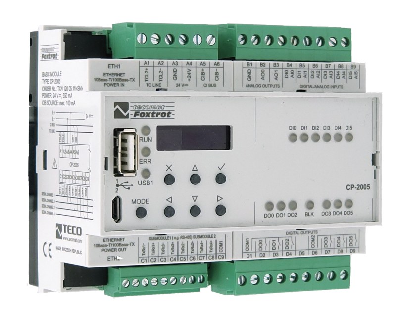
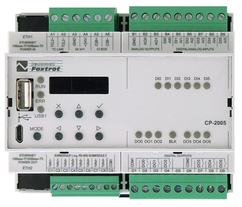
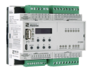
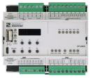
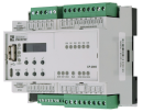
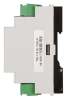
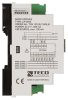
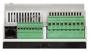
CP-2005 is a second-generation Foxtrot basic module, which is an optimal combination of a central unit with an integrated combination of 12 digital and analog inputs and outputs, compact size occupying a width of 6 modules on a DIN rail. It is thus possible to have a variant with a built-in LTE modem for direct connection to the Internet via a mobile operator.
Of course, there are masters of both system expansion buses - TCL2 (up to 10 addressable modules) and two-wire CIB Common Installation Bus® (up to 32 addressable modules). It can therefore be extended in the same way as other basic modules.
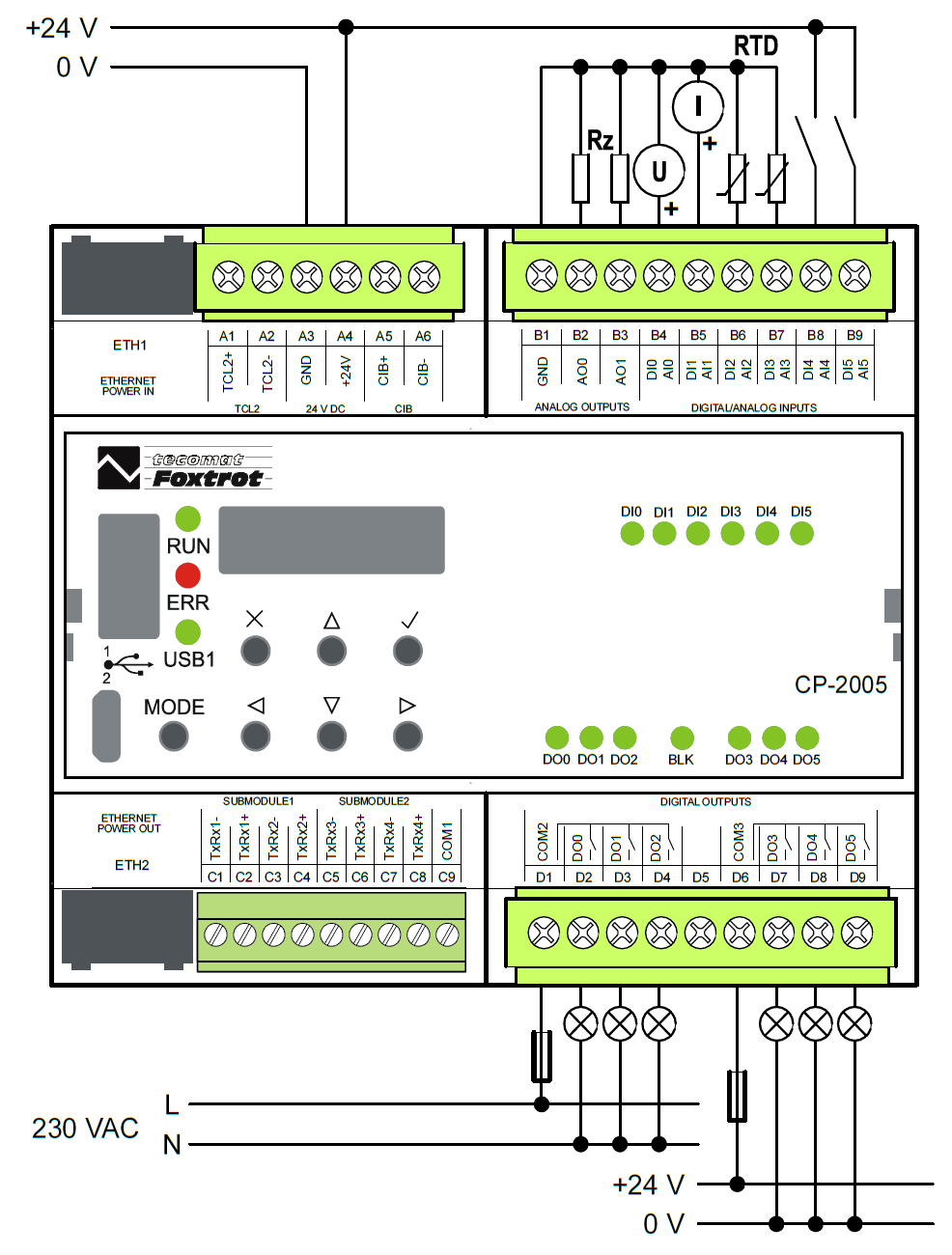
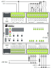
It is equipped with a total of 12 I / Os:
Communication capabilities of the basic module CP-2005:
24 V DC power supply, possibility of direct connection of a backup battery for uninterrupted operation in case of 230 V AC mains failures.
CP-2005 is equipped with a new powerful central unit (CPU series L) with memory
Of course, there are masters of both system expansion buses - TCL2 (up to 10 addressable modules) and two-wire CIB Common Installation Bus® (up to 32 addressable modules). It can therefore be extended in the same way as other basic modules.
It is equipped with a total of 12 I / Os:
- six multipurpose inputs, each of which can be used either as analog or as binary
- two analog outputs for proportional control of various connected devices.
- six separate relay outputs organized into two groups of three with their own common terminal
Communication capabilities of the basic module CP-2005:
- 2x Ethernet interface 100 Mbit / s, each with up to 32 simultaneous connections (programming and general IP communication)
- USB micro (programming)
- USB A for Flas memory, WiFi adapter (client and AP - Access point) etc.
- Variant with built-in LTE modem for direct wireless connection to the Internet via a mobile network operator
- Slots for up to 4 optional serial interfaces RS-485, RS-232
24 V DC power supply, possibility of direct connection of a backup battery for uninterrupted operation in case of 230 V AC mains failures.
CP-2005 is equipped with a new powerful central unit (CPU series L) with memory
- 1 MB for user program,
- 128 MB internal disk for storing files with parallel access from the LAN as a network disk,
- 16MB fast RAM disk
- 128/256 kB Datalobox
- microSD card slot up to 1 TB
- File management is provided by a journaling file system
- Local communication with the user via OLED display (4 lines / graphic) and 6-key keyboard
| Order num. | TXN 120 05.11NSNN |
|---|---|
| Teco code | TXN 120 05.11NSNN |
| Categories | Foxtrot 2 - Basic modules |
| Tags | - |
| System parameters of the central unit | |
|---|---|
| Row of central unit | I |
| User program memory | 1 MB |
| Memory for user variables / including RETAIN variables | 320 kB/48 kB |
| Instruction length | 4 Byte |
| Backup of program source code in PLC | Yes, optional in Mosaic |
| On-line program change in PLC | Yes, including I / O configuration change |
| DataBox - additional internal data memory | 128/257 kB, optional |
| File system - Internal Drive in PLC | 128 MB, journaling file system |
| File system - RAM disk PLC | 16 MB |
| File System - USB Flash Drive | Supported |
| File system - Micro SD card | supported (except for variants with WLAN1) |
| Optional memory card slot | microSD - Card Slot (<= 1TB) |
| Cycle time per 1k of logic instructions | 0,036 ms |
| Cycle time for 1k integer operations | 0,044 ms |
| Cycle time for 1k floating point operations | 0,043 ms |
| Development environment | Mosaic v2018.2 or higher |
| Programming languages | ST, IL, LD, FBD, SFC, CFC |
| RTC - Real time circuit | No |
| RTC - Backup time | typ. 500 hours |
| Integrated Web server | Yes |
| Integrated Datalogger | Yes |
| Access to PLC variables via web API | Yes |
| COM - Communication - IP/Ethernet | |
| Ethernet 10/100 Mb (ETHx) | 2 |
| WLAN1 (internal, optional) | 1 |
| WLAN2 (external via USB host, optional) | 1 |
| LTE interface (LTEx, optional) | 1 |
| Available system modes on ETH and WLAN | UNI, PC, PLC, PLD |
| Available system modes on LTE | UNI - Exchange over UDP, TCP and support SSL / TLS encryption PC - EPSNET UDP / EPSNET TCP |
| TCP / IP protocol | Yes |
| UDP protocol | Yes |
| HTTPS protocol | Yes |
| HTTP protocol | Yes |
| WebSocket protocol | Yes |
| Protocol MODBUS/TCP | Yes |
| SMTP protocol | Yes |
| IEC 60870-5-104 protocol | Yes |
| REST API | Yes |
| COM - USB | |
| USB devices interface | 1x micro-USB |
| USB host interface | 1x USB-A |
| Available system modes on USB | PC |
| COM - Serial channels | |
| max. number of optional serial channels in the basic module | 4 |
| number of slots for optional submodules with interface (MR-013x) | 2 |
| max. number of expanding serial channels on the TCL2 bus | 6 |
| Available system modes on CH5-10 | UNI, CSJ (CAN) |
| Modbus RTU / ASCII master protocol | Yes |
| Modbus protocol RTU/ASCII slave | Yes |
| COM - System buses | |
| TCL2 - system I/O bus | 1x TCL2 master |
| TCL2 - Range of one branch of the system I/O bus | 10 I / O modules + 4 operator panels + 6 serial channels |
| CIB - Common Installation Bus (R): Installation I/O bus | 1x CIB master (100 mA) |
| CIB - Address range of one branch of the installation bus | 32 CFox I/O modules |
| DI - Parameters of binary inputs DC (group A) | |
| Number of inputs in group | 6 |
| Common wire | minus |
| Input type | Type 1 (IEC) |
| Galvanic isolation of inputs from internal/peripheral circuits | No |
| Diagnostics | indication of energized input by LED on module panel |
| Input voltage for log. 0 | 0 V DC; -5 V DC min.; +5 V DC max. |
| Input voltage for log. 1 | 24 V DC; 15 V DC min.; 30 V DC max. |
| Input current at log. 1 (typ.) | 5 mA typ. |
| Delay from log. 0 to log. 1 | 500 μs |
| Delay from log. 1 to log. 0 | 500 μs |
| The minimum width of the captured pulse | 500 μs |
| Notice | Note that the GND terminals in the 24 V DC and ANALOG OUTPUTS arrays they are connected inside the system. It is not desirable to connect the GND terminal in the ANALOG field OUTPUTS with a negative pole power supply system also inputs as it would cross the other the GND terminal has closed the loop and thereby potentially induced interfering signals. |
| HSC - Special functions of binary inputs / counters | |
| Unidirectional counter (UP) | 3x (DI3); (DI4); (DI5) |
| HSC - Counter input parameters | |
| Counter: Input frequency / resolution | 1 kHz |
| Pulse width | min. 500 μs |
| Delay from log. 0 per log. 1 | 500 μs |
| Delay from log. 1 per log. 0 | 500 μs |
| Range of registers | up to 32 bits, 0 to 4 294 967 296 |
| RO - Parameters of binary relay outputs (group A) | |
| Parameters valid for the terminals | DO0 - DO5 |
| Number of relay outputs | 6 |
| Number of output groups | 2 |
| Organization of relay outputs into groups | 3x (DO0-DO2) + 3x (DO3-DO5) |
| Diagnose | Alarm signaling on panel module |
| Switching current | 3 A max., 100 mA min. |
| Switching voltage | 250 V AC max., 5 V AC min., 30V DC max. |
| Short-term output overload - inrush | 4 A max. |
| Current through common clamp | 10 A max. |
| Contact closing time | typ. 10 ms |
| Contact opening time | typ. 4 ms |
| Limit values of switched resistive load | max. 3A at 30 V DC or 230 V AC |
| Switching inductive load limits DC13 | max. 3 A at 30 V DC |
| Switching inductive load limits AC15 | max. 3 A at 230 V AC |
| Switching frequency without load | max. 300 switching / min. |
| Switching frequency with rated load | max. 20 switching / min. |
| Mechanical life | min. 5,000,000 cycles |
| Electrical life at maximum resistive load | min. 100,000 cycles |
| Electrical life at maximum load inductive DC13 | min. 100,000 cycles |
| Electrical life at maximum load inductive AC15 | min. 100,000 cycles |
| Short-circuit protection | No |
| Treatment of inductive load | External RC element, varistor (AC), diode (DC) |
| Insulation voltage between outputs and internal circuits | 3750 V AC |
| Isolation voltage between groups of outputs to each other | 3750 V AC |
| AI - Organization of analog inputs | |
| Total number of analog inputs | 6 |
| Number of inputs per group | 6 |
| Number of analog input groups | 1 |
| Input type | With common clamp |
| Common wire | Minus |
| Galvanic separation from internal circuits | No |
| Diagnostics | overload signaling in status word |
| External power supply | No |
| Digital resolution | 12 bit |
| Converter type | Approximation |
| conversion time | 20 μs |
| Operating modes | periodic input sensing |
| Filtration | low pass filter, digital comb filter 50/60 Hz |
| Insulation potential | 500 V DC between input and internal circuits |
| AI - Analog Input Ranges (Group A) | |
| Voltage | 0 to 10 V / 2,579 mV |
| Voltage | 0 to 2 V / 805.9 μV |
| Input impedance in the voltage signal range | > 20 kΩ |
| Voltage input error - max. error at 25 ° C | ± 0.4% of full scale |
| Voltage input error - temperature coefficient | ± 0.03% of full scale / K |
| Voltage input error - non-linearity | ± 0.07% of full scale |
| Voltage input error - repeatability under steady state conditions | 0.05% of full scale |
| Permissible continuous overload - voltage input | -20 V to +30 V |
| Ccurrent | 0 to 20 mA / 8,059 μA |
| Current | 4-20 mA |
| Input impedance in the current signal range | 100 Ω |
| Current input error - maximum error at 25 ° C | ±0.4% of full scale |
| Error current input - temperature coefficient | ± 0.03% of full scale / K |
| Error current input - nonlinearity | ± 0.07% of full scale |
| Error current input - repeatability at steady-state conditions | 0.05% of full scale |
| Permissible continuous overload - current input, resistance 100 R | ± 5 V / 50 mA max |
| Open input detection | Yes, in status word (under-range - only 4 - 20 mA range) |
| Passive sensor | Pt1000, W100 = 1,385 (-90 to +400 °C) |
| Passive sensor | Pt1000, W100 = 1,391 (-90 to +400 °C) |
| Passive sensor | Ni1000, W100 = 1,500 (–60 to +200 ° C) |
| Passive sensor | Ni1000, W100 = 1.617 (-60 to +200 ° C) |
| Passive sensor | Resistance transmitter 0-2 kOhm |
| Passive sensor | Resistance transmitter 0-200 kOhm |
| Passive sensor | KTY81-121; PTC thermistor (-55 to + 125 °C) |
| Passive sensor | NTC Thermistor 5k / 25 °C (–40 to + 125 °C) |
| Passive sensor | NTC Thermistor 10k / 25 °C (-40 to + 125 °C) |
| Passive sensor | NTC Thermistor 12k / 25 °C (-40 to + 125 °C) |
| Passive sensor | NTC Thermistor 15k / 25 °C (-40 to + 125 °C) |
| Passive sensor | NTC Thermistor 20k / 25 °C (-40 to + 125 °C) |
| Input impedance in signal range RTD | > 20 kΩ |
| Resistance measurement error - maximum error at 25 ° C | ± 0.5% of full scale |
| Resistance measurement error - temperature coefficient | ± 0.05% of full scale / K |
| Resistance measurement error - non-linearity | ± 0.09% of full scale |
| Resistance measurement error - repeatability at steady conditions | 0.07% of full scale |
| Detection of disconnected sensor | yes, in status word, range overflow |
| AO - Analog output parameters | |
| Common wire of group | minus |
| Galvanic isolation from internal circuits | No |
| Output type | active voltage output |
| Converter resolution | 12 bit |
| conversion time | 10 μs |
| Analog output error - maximum error at 25 ° C | ± 2% of full scale |
| Analog output error - temperature coefficient | ± 0.3% of full scale / K |
| Analog output error - linearity | ± 0.7% of full scale |
| Analog output error - repeatability under steady state conditions | ± 0.5% of full scale |
| Voltage output - voltage | 0 - 10,5 V |
| Voltage output - Resolution 1 LSB | 2,589 mV |
| Voltage output - maximum output current | 10 mA |
| Power supply | |
| Supply voltage, tolerances | 24 V DC, +25%, -15%, SELV |
| Maximum power input | 10 W |
| Module thermal/power loss | 12 W |
| Internal protection | Yes, PTC reversible fuse |
| CIB branch power supply - parameters of the built-in master | 1x 100 mA/ 24 V DC |
| Power supply from ETH, passive PoE - input (appliance) | ETH1/Power In |
| Power supply from ETH, passive PoE - output (source) | ETH2 / Power out, jumper configuration |
| Power supply from ETH, passive PoE - injector parameters | 24 V DC, 1A |
| Size and weight | |
| Weight approx. | 200 g |
| Product dimensions (width x height x depth) | 105 x 90 x 62 mm |
| Module width in multiples of M (17.5 mm) | 6M |
| Operating conditions, product standards | |
| Product standard | ČSN EN 61131-2:2008 (idt IEC 61131-2:2007) - Programmable control units |
| Protection class of electrical object | II, according to ČSN EN 61140 ed.3: 2016 (idt IEC 61140:2016) |
| IP rating (Ingress Protection) according to ČSN EN 60529: 1993 (idt IEC 529: 1989) | IP20 |
| Operating areas | Normal, acc. ČSN 33 2000-1 ed.2: 2009 (mod IEC 60354-1:2005) |
| Degree of pollution | 1, according to ČSN EN 60664-1 ed.2:2008 ( idt IEC 60664-1:2007) |
| Overvoltage category installation | II, according to EN 60664-1 ed_2: 2008 (idt IEC 60641-1: 2007) |
| Type of device | Module on DIN rail |
| Working position | Vertical |
| Type of operation (operating frequency) | Continuous |
| Ambient operating temperatures | -20 °C to + 55 °C |
| Operating temperature maximum (° C) | +55°C |
| Operating temperature minimum (° C) | -20°C |
| Operating relative humidity | from 10 % up to 95 % without condensation |
| Operating atmospheric pressure | min. 70 kPa (<3,000 m above sea level) |
| Storage temperatures | –25 °C to +70 °C |
| Electromagnetic compatibility, Mechanical endurance | |
| Electromagnetic compatibility / Emission | B, according to EN 55032 ed. 2: 2017 (idt CISPR 32: 2015) |
| Emmisions - note | In premises where the use of radio and television receivers can be expected to be used a distance of 10 m from these devices may cause radio interference. In such a case, the user may be required to take appropriate action. |
| Electromagnetic compatibility / Immunity | min. as required by EN 61131-2: 2007 |
| Sinusoidal vibration endurance | 10 Hz to 57 Hz, amplitude 0,075 mm, 57 Hz to 150 Hz, acceleration 1 G (Fc test according to EN 60068-2-6: 1997 (idt IEC 68-2-6: 1995), 10 cycles per axis.) |
| Packaginng, transportation, storage | |
| Description | The module is packed in a paper box according to the internal packing instructions. The package includes the following documentation. The outer packaging is carried out according to the scope of the order and the method of transport to the transport a package bearing the transport labels and other particulars necessary for transport. Transport from the manufacturer is carried out in the manner agreed upon when ordering. Product transport the customer's own means must be carried out by covered means of transport, in the specified position label on the packaging. The box must be stowed so as to prevent spontaneous movement a damage to the outer packaging. The product must not be exposed to direct weathering during transport and storage influences. Transport is allowed at temperatures from -25 ° C to +70 ° C, relative humidity 10% up to 95% (non-condensing) and a minimum atmospheric pressure of more than 70 kPa. Storage of the product is only allowed in clean rooms without conductive dust, aggressive gases and vapors. The most suitable storage temperature is 20 ° C |
| Installation | |
| Assembly description | Switchboard mounting |
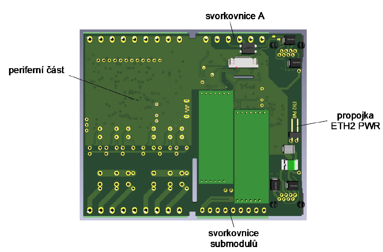
| Assembly description | The basic module is mounted vertically on the U-rail ČSN EN 50022. The installation of the assembly (basic module and peripheral modules, if applicable) is performed according to TXV 004 50. |
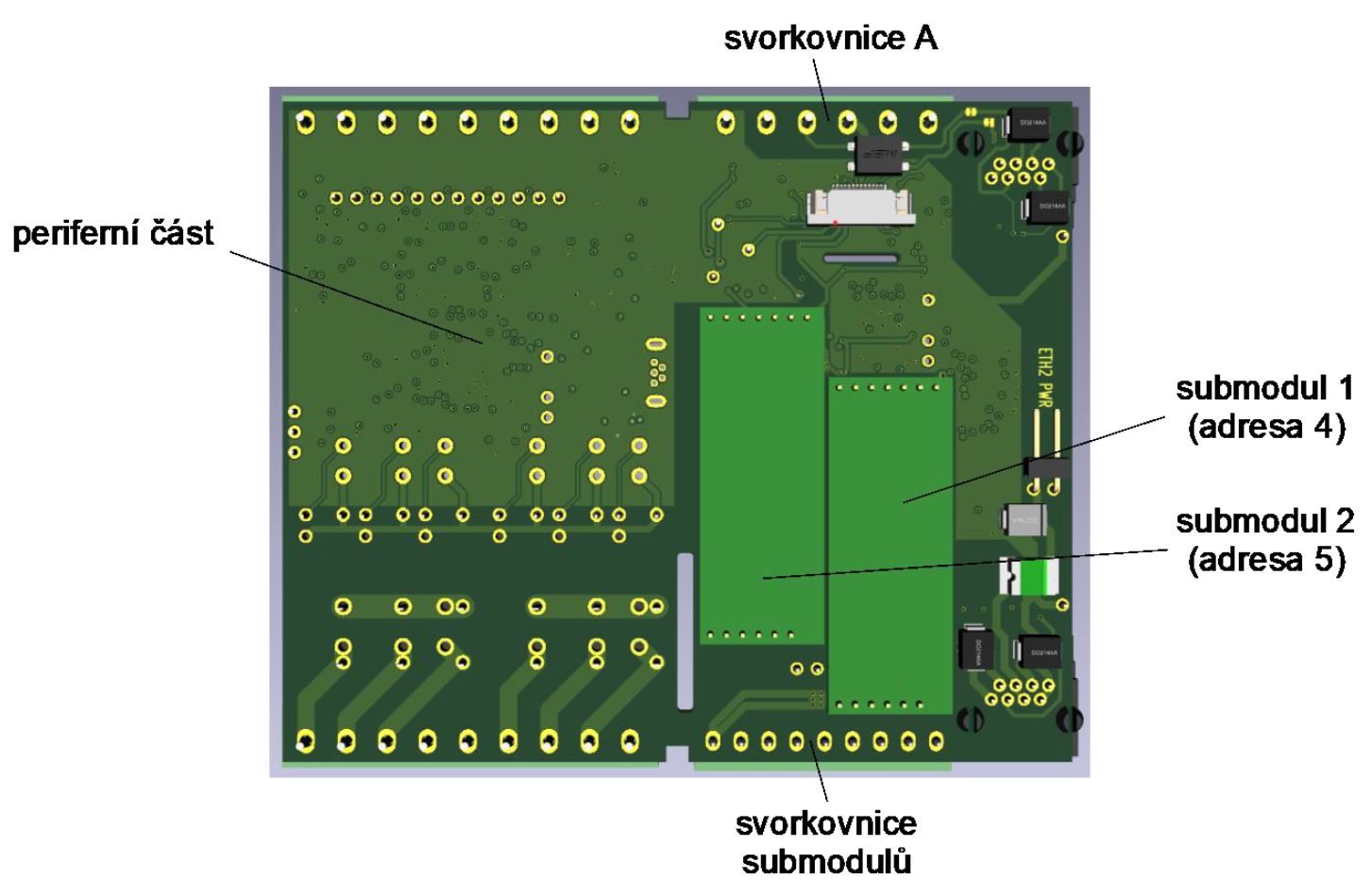
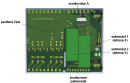
| Exchangeable submodules | The optional MR-013x submodules of the serial interface are mounted in the base module CP-2007 on the bottom plate, which is accessible after removing the bottom of the housing. We only handle the module without power supply! |
| Connection | |
| Connection of power and system communication | connector with 2.5 mm2 screw terminal |
| Connection of inputs / outputs | connector with screw terminal 2.5 mm2 |
| Ethernet | RJ-45 |
| Serial channels | screw-type connector 9x 1.5 mm2 |
| USB device connection | type micro B |
| USB host connection | type A |
| Module operation | |
| Module configuration | The module is operated, set and diagnosed from the MOSAIC programming environment. It is also possible to connect to the PLC using a web browser on port 8080. If the PLC has an IP address set eg 192.168.134.178 (default address on port ETH1, port ETH2 has DHCP enabled), just enter the address in the form http://192.168.134.178:8080 and the web browser displays the PLC configuration pages. |
| Commissioning | The module is ready for operation after connection of the supply voltage. The MODE button is available on the module panel to display the currently set IP address of the Ethernet interface. Parameters of all interfaces are set in the Mosaic programming environment. The exact setup procedure is given in the TXV 004 50 documentation. |
| Module diagnostics | The basic diagnostic system of the module is part of its standard software. It operates from module power on and operates independently of the user. Diagnostic error states of the module and connected peripheral modules of the assembly are signaled on the module display and are available for processing by the master system. For more information, see TXV 004 50. |
| Maintenance | |
| Description | The module does not require any maintenance under general installation conditions. |
| Notice | Because the module contains semiconductor components, it is necessary to follow the principles for working with electrostatic sensitive components when handling the removed cover. It is not allowed to directly touch the printed circuit boards without protective measures !!! |
| Warranty | |
| Generally | Warranty and complaint conditions are governed by the Terms and Conditions of Teco a.s. |
| Notice | You must meet all the conditions of this documentation before turning on the system. The system must not be put into service unless it has been verified and confirmed that the machinery meets the requirements of Directive 89/392 / EEC, in so far as it applies to it. Documentation subject to change. |
HW documentation
CP-2005 - Basic documentation (en)
4.81 MB, (EN)
User manuals
CP-2005 - User's Guide (en)
2.69 MB, (EN, RU, DE)
Foxtrot 2 - Serial communication (en)
2.25 MB, (EN, RU, DE)
Files for designers
Foxtrot 2 - library of elements in DXF and DWG formats, v. 2025/08.
21.80 MB
Foxtrot 2 - element library for SchemataCAD, v. 2025/08.
6.96 MB
EC - Declaration of Conformity
Foxtrot 2 - EC Declaration of conformity (en)
590.59 kB, (EN, RU, DE, UA)


WiFi - USB miniature adapter
TP-LINK TL-WN725N
WiFi - USB miniature adapter; 802.11b / g / n, 150 Mbps, USB 2.0
- DRC-60B, example of CP-2005 backup power supply - ...Dimensions 40 x 90 x 100 mm Fig. 1. Example of CP-2005 backup power supply Notes: The switched-off power supply, after connecting only the batteries, does no...
- DRC-40B, CP-2005 power backup example - ...Dimensions 40 x 90 x 100 mm Fig. 1. Example of CP-2005 backup power supply Notes: The CP-2005 module does not have a "potential-free contact" binary input mo...
- Example of calculating the capacity of the backup battery for the CP-2005 power supply - ...f the required battery capacity for backup power supply of the basic Foxtrot module. The typical power consumption of the CP-2005 basic module, with the relays open, is approx. 3W (each closed relay adds approx. 0.2W). The quiescent power of th...
- DRC-40A, power supply backup of CP-2005 using 12V voltage - ...Dimensions 40 x 90 x 100 mm Fig. 1. Example of CP-2005 backup power supply Notes: The CP-2005 module does not have a "potential-free contact" binary input mo...
- CP-2005 - The basic module CP-2005 is the basic module of the Foxtrot 2 control system. It is in standard version on DIN rail, in 6M cover (for dimensions of box see chapter 13.2.2 6M mechanics on DIN rail ), equipped with four removable terminal blocks. It...
- Connecting multiple CF-2141s to a single CP-2005 - The following example shows the data connection of several CF-2141 master modules to one Foxtrot 2 basic module using the SX-1161 Ethernet switch . The example does not show the power connection. It depends on the location of individual CF-21...
- Submodules MR-0130 - MR-0134 - serial channels - ...d directly to the fast internal bus of the base module. Optional submodules are fitted to the base plate of the CP-2005 on the bottom plate from the outside (surface towards the bottom of the module housing) to the positions indicated in...
- CP-2007 - ...is equipped with six removable terminal blocks. For more information on possible casting options, see the introduction to CP-2005. Fitting I/O: Power supply 24 VDC, power consumption max. 10W (see chapter 2.2 for information on p...
- CP-2080 - ...d with two serial channel submodules. For more information on possible casting options, see the introduction to CP-2005. Fitting I/O Power supply 24 VDC, power consumption max. 10 W (for power supply see chap. 2.2 )...
- CP-2090 - ...ipped with six removable terminal blocks. For more information on possible casting options, see the introduction to CP-2005. This module cannot be fitted with LTE and a large display. The module is not equipped with any inputs and outputs...
- Foxtrot 2 Internal LTE Modem - Key Features - Internal LTE modems for the Foxtrot 2 series, such as the CP-2007, CP-2005, CP-2080, and others, provide full support for key European bands B1, B3, B7, B8, and B20; the supported frequency bands are listed below. The CP-2xxx is equipped with an...
- Foxtrot 2 - Shifts to two! - ...y with one, two, three or max. With four serial channels. In the first phase, RS-232 and RS-485 are ready. CP-2005 , CP-2080 ; Foxtrot 2 width of six modules has a built-in 4G / LTE modem. The full integration of Foxtrot into...
- CF-2141, CF-2142, TF-2121 - examples of connecting multiple modules to a single CP-2xxx - ...to connect the modules in series, as shown in the following figure. Fig. 1: Four CF-2142 units connected to a single CP-2005 CF-2141 and CF-2142 - Maximum Configuration for a Single CP-2xxx A maximum of 7 CF-2141 units or 7 CF...
- Foxtrot 2 with LTE modem - ...he smallest CP-2090, are also available with an internal LTE modem. The designation of the control panel is then eg CP-2005.11NSLN (TXN 120 05-11NSLN), where the letter L means LTE - see the table Designation of variants of basic modules TE...
- Power dissipation of modules for calculation of switchboard heating - ...TXN 120 00.11NDNN CP-2000 CP-2000 9,0 W TXN 120 05.11NSLN CP-2005, 6M, 128 KB databox, LTE, 6x AI/DI, 6x DO relay, 2x AO CP-2005 12,0 W TXN 12...
- FIRST INTRODUCTION TO TECOMAT FOXTROT 2 PROGRAMMABLE CONTROLLERS - ...moving the bottom of the housing Basic arrangement of Foxtrot 2 Fig 2. Basic module CP-2005 without WLAN1 or LTE1 (TXN 120 05.x1NSNN) Fig 3. Basic module CP-2005 with LTE1 interface (TXN 120 05.x1N...
- CF-2141 CIB master for Foxtrot 2 - The CF-2141 module is a CIB bus master for the Foxtrot 2 system (CP-2xxx central units), which allows the connection of one CIB line (up to 32 CIB units). The CF-2141 module provides internally a full-fledged power supply for CIB lines (it contain...
- CF-2141 CIB master for Foxtrot 2_kopie335 - The CF-2141 module is a CIB bus master for the Foxtrot 2 system (CP-2xxx central units), which allows the connection of one CIB line (up to 32 CIB units). The CF-2141 module provides internally a full-fledged power supply for CIB lines (it contain...
- CP-2005 ETH2 static IP and Tecoroute problem - HI, I'm experiencing the following problem with CP-2005 with 5.8 firmware: I set ETH2 to static IP and manually configured the parameters and then it won't connect to Tecoroute also the PLC cannot be reached within other networks. With DHCP it wor...
- R-LC-0202B-A weird thermosensor values - I've encountered an anomaly with R-LC-0202B-A's thermometering. I have a setup which has CP-2005, and these radio modules connected via the C-RF-001M-A radio master. Randomly happens with any module on the radio network they send, their thermometer...
- Error E-B1-88-1006 - I'm getting this error, it happened on a few PLCs, all of them are CP-2005. What could cause this error? The TCL2 line is closed with the included resistor and connected in the proper bus structure. IT-1604 module is on the line. Thank you i...
- Error E-B1-70-2001 IO error - Hi, Yesterday a CP-2005 stopped and couldn't be restarted first, just after more retries. Here is a log extract: What does this error mean exactly? What could have caused this error? 2023-04-23 11:53:38.935023 Error E-B1-70-2001 IO error: Sub I...
- Error E-B1-88-1006 - ...connect to the unit. I cannot determine the cause, I would try to check and possibly update the firmware of the central unit CP-2005 (the current version is now 6.6) and if the error were to recur even with this fw version, then it would probably be...
- Analog input - ...ly RTD (temperature sensors) connection (see https://catalog.tecomat.cz/en/product/cp-1000#params). Other types of CPUs like CP-2005 (https://catalog.tecomat.cz/en/product/cp-200511nsnn#params), CP-2007 (https://catalog.tecomat.cz/en/product/cp-20071...