
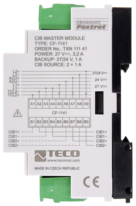

CF-1141TXN 111 41
CF-1141; CIB; 2x CIB master with power supply, for a total of 64 slaves, communication with CP: TCL2 - only for Foxtrot1
| DI | |
|---|---|
| DI/AI | |
| DO | |
| AI | |
| AO | |
| COM | 1x TCL2 slave 2x CIB master |
| SENSOR |
| Picture | Variant | Variant description |
|---|---|---|

|
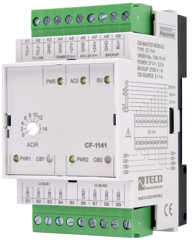
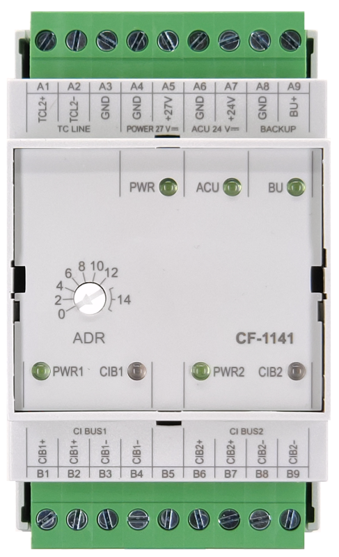
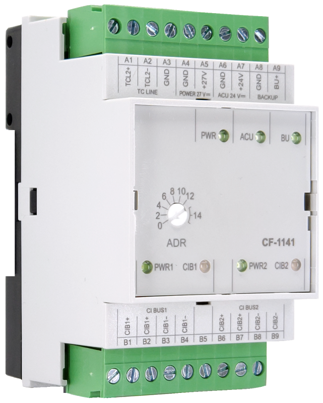
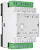
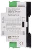
CF-1141 |
The CF-1141 module is a two-channel CIB master with a separator
perimeter. Each channel allows the connection of 32 modules to
maximum current 1A. Communication with the basic module
takes place via the TCL2 interface.
perimeter. Each channel allows the connection of 32 modules to
maximum current 1A. Communication with the basic module
takes place via the TCL2 interface.
| Order num. | TXN 111 41 |
|---|---|
| Teco code | TXN 111 41 |
| Categories | CFox - System Modules |
| Tags | - |
| COM - System buses | |
|---|---|
| TCL2 - system I/O bus | 1x TCL2 slave |
| The communication rate of the system I / O bus | 345 kbps |
| System I / O bus terminating resistor | 120 Ω |
| CIB - Common Installation Bus (R): Installation I/O bus | 2x CIB master (2x 1 A) |
| CIB - Address range of one branch of the installation bus | 32 CFox I/O modules |
| Power supply | |
| Nominal supply voltage (V) | 24 V DC |
| Supply voltage, tolerances | 24 V DC ± 15% external power supply |
| Supply voltage when backing up with an external battery | 27 V DC, +10%, –15%, SELV |
| Maximum power input | 85 W |
| Module thermal/power loss | 4 W |
| Maximum current consumption (mA) | 3,125 A |
| Galvanic separation of power supply from internal circuits | No |
| Description of power supply | The difference between the typical and the maximum power is given by the possible load on the CIB buses |
| Possibility of backing up the power supply of the basic module and CIB | Yes, by battery 2x 12 V DC, 1x 24 V DC |
| Battery parameters | Pb battery 24V |
| Continuous charging | Yes, through charging circuitry in the base module |
| Charging current | 2 A max |
| Internal protection оf backup battery | Yes |
| Size and weight | |
| Weight approx. | 125 g |
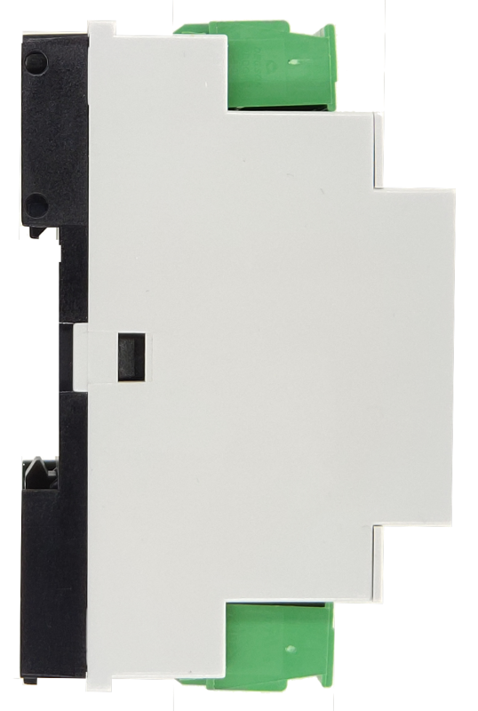
| Product dimensions (width x height x depth) | 52 x 90 x 58 mm |
| Module width in multiples of M (17.5 mm) | 3M |
| Module width | 52 mm |
| Module height | 90 mm |
| Module depth | 58 mm |
| Operating conditions, product standards | |
| Product standard | ČSN EN 61131-2 ed.2: 2008 (IEC 61131-2: 2007) и ČSN EN 60730-1 ed.4: 2017 (EN 60730-1: 2016) |
| Protection class of electrical object | III, according to ČSN EN 61140 ed.3: 2016 (idt IEC 61140:2016) |
| IP rating (Ingress Protection) according to ČSN EN 60529: 1993 (idt IEC 529: 1989) | IP20 |
| Operating areas | Normal, acc. ČSN 33 2000-1 ed.2: 2009 (mod IEC 60354-1:2005) |
| Degree of pollution | 1, according to ČSN EN 60664-1 ed.2:2008 ( idt IEC 60664-1:2007) |
| Overvoltage category installation | I, according to ČSN EN 60664-1 ed_2:2008 (idt IEC 60641-1:2007) |
| Type of device | Module on DIN rail |
| Working position | Vertical |
| Type of operation (operating frequency) | Continuous |
| Ambient operating temperatures | -20 °C to + 55 °C |
| Operating temperature maximum (° C) | +55°C |
| Operating temperature minimum (° C) | -20°C |
| Operating relative humidity | from 10 % up to 95 % without condensation |
| Operating atmospheric pressure | min. 70 kPa (<3,000 m above sea level) |
| Storage temperatures | –25 °C to +70 °C |
| Electromagnetic compatibility, Mechanical endurance | |
| Electromagnetic compatibility / Emission | B, according to EN 55032 ed. 2: 2017 (idt CISPR 32: 2015) |
| Emmisions - note | In premises where the use of radio and television receivers can be expected to be used a distance of 10 m from these devices may cause radio interference. In such a case, the user may be required to take appropriate action. |
| Electromagnetic compatibility / Immunity | min. as required by EN 61131-2: 2007 |
| Sinusoidal vibration endurance | 10 Hz to 57 Hz, amplitude 0,075 mm, 57 Hz to 150 Hz, acceleration 1 G (Fc test according to EN 60068-2-6: 1997 (idt IEC 68-2-6: 1995), 10 cycles per axis.) |
| Packaginng, transportation, storage | |
| Description | The module is packed in a paper box. This documentation is also part of the package. The outer packaging is carried out according to the scope of the order and the method of transport in a transport package provided with labels and other data necessary for transport. The product must not be exposed to direct weather conditions during transport and storage. Malting of the product is only allowed in clean rooms without conductive dust, aggressive gases and vapors. The most suitable storage temperature is 20 ° C |
| Installation | |
| Assembly description | Mounting on DIN rail 35 / 7.5 (U) in the switchboard |
| Attention! | The device may contain parts with dangerous voltages, covers being removed, or cabling manipulated, or disconnect the appropriate circuits or turn off the power !. |
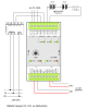
| Connection | |
| Connection of power and system communication | connector with 2.5 mm2 screw terminal |
| Serial channels | screw-type connector 9x 2.5 mm2 |
| Module operation | |
| Module configuration | The module is operated, set up and diagnosed from the Mosaic development environment. |
| Module diagnostics | The basic diagnostic system of the module is a part of its standard software. It operates from module power on and operates independently of the user. Diagnostic error states of the module and connected peripheral modules of the assembly are signaled |
| Maintenance | |
| Description | The module does not require any maintenance under general installation conditions. The operations in which a part of the module has to be dismantled must always be carried out with the supply voltage disconnected. |
| Notice | Because the module contains semiconductor components, it is necessary to follow the principles for working with electrostatic sensitive components when handling the removed cover. It is not allowed to directly touch the printed circuit boards without protective measures !!! |
| Warranty | |
| Generally | Warranty and complaint conditions are governed by the Terms and Conditions of Teco a.s. |
| Notice | You must meet all the conditions of this documentation before turning on the system. The system must not be put into service unless it has been verified and confirmed that the machinery meets the requirements of Directive 89/392 / EEC, in so far as it applies to it. Documentation subject to change. |
HW documentation
CF-1141 - basic documentation
70.95 kB, (CS, EN, RU, DE)
CF-1141 - Basic documentation
1.69 MB, (EN)
Files for designers
Foxtrot 2 - library of elements in DXF and DWG formats, v. 2025/08.
21.80 MB
Foxtrot 2 - element library for SchemataCAD, v. 2025/08.
6.96 MB
EC - Declaration of Conformity
Foxtrot - EC Declaration of conformity
295.20 kB, (EN, RU, DE, UA)
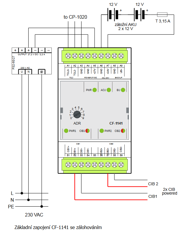
- CF-1141 external CIB master - The CF-1141 master module provides the power for and operation of two CIB buses (branches), each with a maximum of 32 connected peripheral modules (units). The CF-1141 provides identification, addressing, configuration and operation of connected per...
- Power dissipation of modules for calculation of switchboard heating - ...aster, for up to 64 slaves, TCL2, Din rail module RF-1131 0,8 W TXN 111 41 CF-1141; CIB 2x master CIB with power supply, for 64 slaves CF-1141 4,0 W TXN 111 62...
- CIB power supply – principles, optimization - ...modification of the application configuration. Fusing and protection of the CIB bus power supply The CF-1141 external master as well as the CIB internal master, and in fact the whole Foxtrot basic module, which contains an...
- CIB characteristics - ...is provided by a standard 27.2 VDC or 24 VDC source connected to the bus via internal separation circuits ( CP-1000 , CF-1141 ) or an external decoupling module C-BS-0001M . The power supply can also be used for powering the Foxtrot syst...
- CIB bus – principles of design and installation - ..., CP-10x6 and 10x8-CP are fitted with one master CIB; additional modules can be connected via external CIB master modules CF-1141 (maximum 4 master modules CF-1141 to one basic module). Each external master module CF-1141 perm...
- The FOXTROT peripheral modules - ...nd special modules. Up to 10 peripheral modules can be connected to the TCL2 bus on the central module. Furthermore, the CF-1141 (dual external CIB) master modules can be connected to the central module via the TCL2 bus, as well as other special...
- CP-1000, power supply without a backup - ...the CP-1000 basic module. On the A connector is terminated the system TCL2 bus (primarily for connecting the external CF-1141 and RF-1131 ) master modules, and the serial communication channel CH1 (usually for GSM modem connection). &nb...
- FOXTROT – the basic and peripheral modules, power supply - ...ains a terminal of TCL2 system bus (for connecting peripheral Foxtrot modules, control panels and external master modules CF-1141 and RF-1131 ) and the serial communication channel CH1 (usually for GSM modem connection). The C connector co...
- TCL2 bus – the principles of design and installation - The peripheral modules on the TCL2 bus (e.g. IB-1301) of one PLC Foxtrot configuration (i.e. all peripheral modules controlled by one basic module) must be interconnected via a bus connection, which is plugged in the terminals in the upper left edg...
- RF master RF-1131 - The product is no longer for sale The RF master implements communication with RF peripheral modules and transmits the acquired data via the system communication bus (TCL2) to the superior basic module. The master is implemented as an externa...
No data available.