


BDM-024-V/1-R1-CIBBDM-024-V/1-R1-CIB
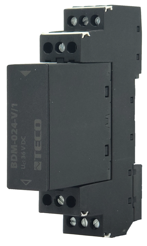
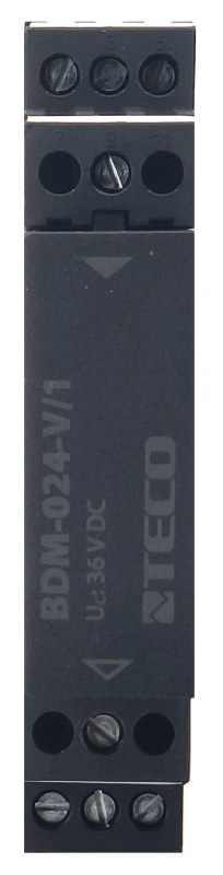
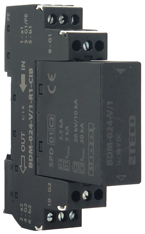
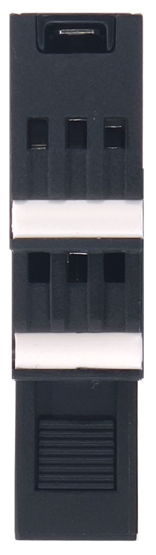
BDM-024-V/1-R1-CIB; Lightning arrester for CIB, 24V/1A, ST1+2+3
| DI | |
|---|---|
| DI/AI | |
| DO | |
| AI | |
| AO | |
| COM | |
| SENSOR |
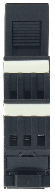
| Picture | Variant | Variant description |
|---|---|---|

|
BDM-024-V/1-R1-CIB |
BDM-024-V / 1-FR1-CIB
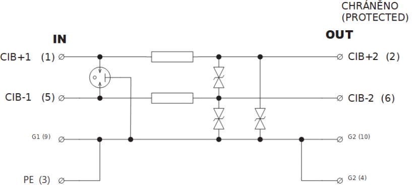
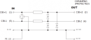
Lightning current arrester with two-stage overvoltage protection designed for the CIB bus
installation at the entrance to the building near the protected equipment, at the interface of zones LPZ 0 – LPZ 1 and higher
can also be used to protect the interfaces of control systems MaR, EZS, EPS, etc.
against longitudinal overvoltage (line - protective earth) rough protection and against transverse overvoltage (core - core, GND) rough and fine overvoltage protection
removable module, coupling impedance (R - resistance), line separated from protective earth by lightning arrester
| Order num. | 1220201058 |
|---|---|
| Teco code | BDM-024-V/1-R1-CIB |
| Categories | CFox - System Modules |
| Tags | - |
| Properties of surge protectors | |
|---|---|
| Type of SPD | D1, C2 |
| Connection (input - output) | clamps - clamps |
| Location of SPD | ST 1+2+3 |
| Rated voltage | 24V DC |
| Highest continuous operating voltage Uc (DC) | 36 V DC |
| Highest continuous operating voltage Uc (AC) | 25 V AC |
| C2 rated discharge current (8/20 µs) per core In | 10 kA |
| C2 rated discharge current (8/20 µs) GND-PE In | 10 kA |
| C2 total discharge current (8/20 µs) of the core-PE ITotal | 20 kA |
| D1 impulse discharge current (10/350 µs) per core Iimp | 2,5 kA |
| D1 total discharge current (10/350 µs) of the core-PE ITotal | 5 kA |
| C3 protection voltage level core-core mode at 1 kV / µs Up | 46 V |
| C3 protection voltage level mode GND-PE at 1 kV / µs Up | 550 V |
| C3 protective voltage level core-GND mode at 1 kV / µs Up | 46 V |
| Vein-vein response time "ta" | 1 ns |
| GND-PE response time "ta" | 100 ns |
| Vein-GND "ta" response time | 1 ns |
| Series resistance on core R | 0,8 Ω |
| Core-vein cutoff frequency f | 4 MHz |
| Operating conditions, product standards | |
| Product standard | ČSN EN 61643-21+A1,A2: 2002 |
| IP rating (Ingress Protection) according to ČSN EN 60529: 1993 (idt IEC 529: 1989) | IP20 |
| Operating areas | Normal, acc. ČSN 33 2000-1 ed.2: 2009 (mod IEC 60354-1:2005) |
| Type of device | Module on DIN rail |
| Working position | Vertical |
| Type of operation (operating frequency) | Continuous |
| Ambient operating temperatures | -40 °C to + 70 °C |
| Operating temperature maximum (° C) | +70°C |
| Operating temperature minimum (° C) | -40°C |
| Packaginng, transportation, storage | |
| Description | The module is packed in a paper box. This documentation is also part of the package. The outer packaging is carried out according to the scope of the order and the method of transport in a transport package provided with labels and other data necessary for transport. The product must not be exposed to direct weather conditions during transport and storage. Malting of the product is only allowed in clean rooms without conductive dust, aggressive gases and vapors. The most suitable storage temperature is 20 ° C |
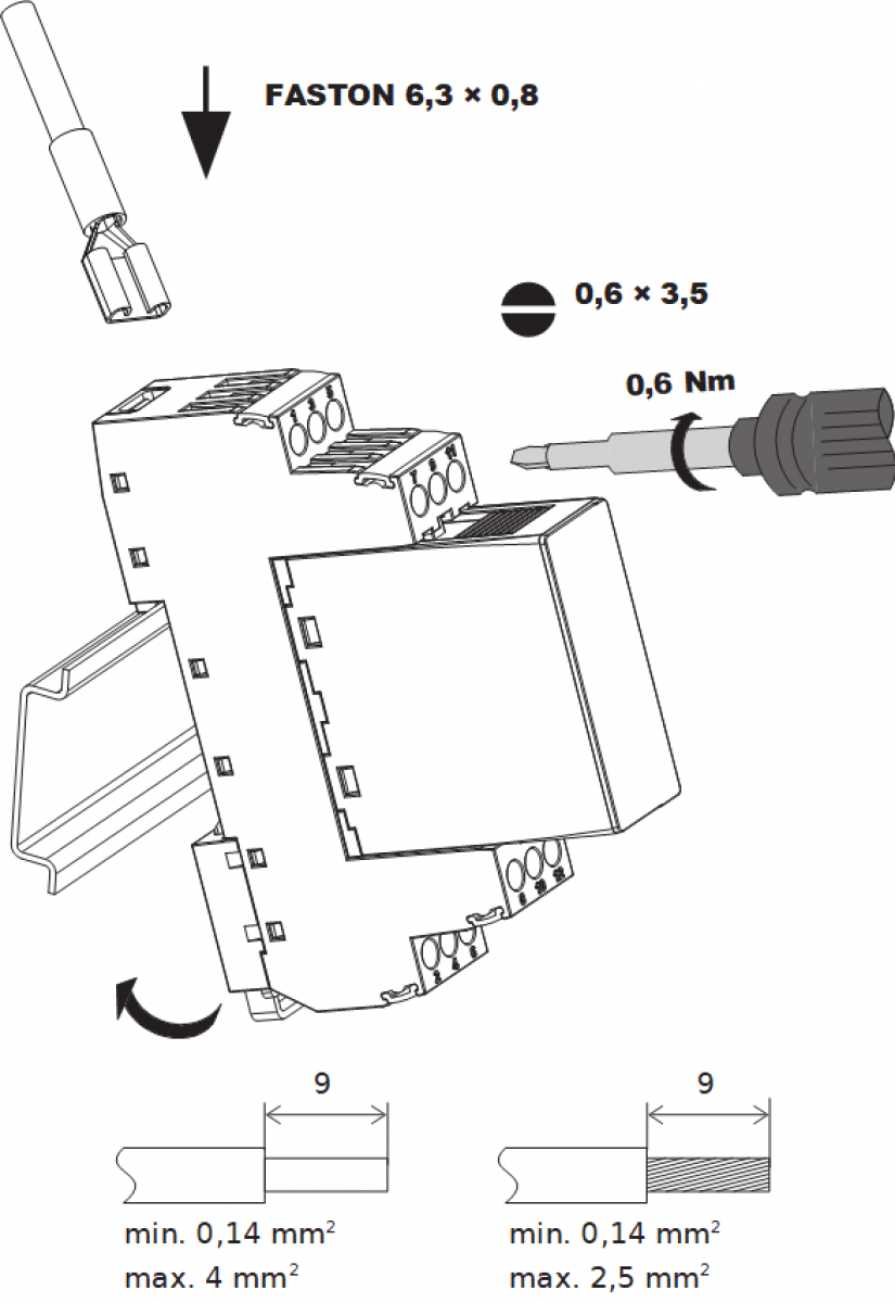
| Installation | |
| Assembly description | Mounting on DIN rail 35 / 7.5 (U) in the switchboard |
| Connection | |
| Cross-section of connected wires fixed (min) | 0,14 mm2 |
| Cross-section of connected wires fixed (max) | 4 mm2 |
| Cross-section of connected wires stranded (min) | 0,14 mm2 |
| Cross-section of connected wires stranded (max) | 2,5 mm2 |
| Maintenance | |
| Description | The module does not require any maintenance under general installation conditions. |
Files for designers
BDM-024 - technical drawing DXF
178.64 kB
No data available.
No data available.