

C-RI-0401R-LOGUS goldTXN 133 47.LTDU
C-RI-0401R-LOGUS gold; CIB, Indoor IR receiver / transmitter, sensors: 1x light intensity, 1xtemperature, 1x AI / DI
| DI | |
|---|---|
| DI/AI | 1x DI/AI |
| DO | |
| AI | |
| AO | |
| COM | 1x CIB slave 1x IR receiver / transmitter |
| SENSOR | 1x Temperature |
| Picture | Variant | Variant description |
|---|---|---|

|
C-RI-0401R-LOGUS, white, TBR | Color: White |

|
C-RI-0401R-LOGUS, ivory, TMF | Color: Ivory |

|
C-RI-0401R-LOGUS, ice, TGE | Color: Ice |

|
C-RI-0401R-LOGUS, Pearl, TPE | Color: Pearl |

|
C-RI-0401R-LOGUS, aluminum, TAL | Color: Aluminum |

|
C-RI-0401R-LOGUS, gray, TIS | Color: Grey |

|
C-RI-0401R-LOGUS black | Color: Black |

|
C-RI-0401R-LOGUS gold | Color: Gold |
C-RI-0401R-LOGUS; CIB. Indoor IR receiver / transmitter, sensors: 1x light intensity, 1x temperature, 1x AI / DI
| Order num. | TXN 133 47.LTDU |
|---|---|
| Teco code | TXN 133 47.LTDU |
| Categories | CFox - LOGUS, Covers and devices |
| Tags | - |
| COM - System buses | |
|---|---|
| CIB - Common Installation Bus (R): Installation I/O bus | 1x CIB slave |
| DI - Organization of binary inputs | |
| Total number of binary inputs | 1 |
| DI - Parameters of binary inputs DC (group A) | |
| Combined input type | DI/AI Active, for sensing potential-free contacts and measuring resistance sensors |
| Galvanic isolation of inputs from internal/peripheral circuits | No |
| Diagnostics | signaling of excited input in Mosaic |
| Input current at log. 1 (typ.) | 3,3 mA |
| Delay from log. 0 to log. 1 | 10 ms |
| Delay from log. 1 to log. 0 | 300 ms |
| The minimum width of the captured pulse | 10 ms |
| Max. measuring voltage on the connected contact | 3,3 V DC |
| AI - Organization of analog inputs | |
| Total number of analog inputs | 1 |
| Common wire | Plus |
| Galvanic separation from internal circuits | No |
| External power supply | No |
| Digital resolution | 12 bit |
| Converter type | Approximation |
| conversion time | 500 μs |
| AI - Analog Input Ranges (Group A) | |
| Parameters valid for inputs on the terminals | DI/AI1 |
| Passive sensor | Pt1000, W100 = 1,385 (-90 to +320 °C) |
| Passive sensor | Pt1000, W100 = 1,391 (-90 to +320 °C) |
| Passive sensor | Ni1000, W100 = 1,500 (–60 to +200 ° C) |
| Passive sensor | Ni1000, W100 = 1.617 (-60 to +200 ° C) |
| Passive sensor | Resistance transmitter 0-160 kOhm |
| Passive sensor | KTY81-121; PTC thermistor (-55 to + 125 °C) |
| Passive sensor | NTC Thermistor 12k / 25 °C (-40 to + 125 °C) |
| DI: Voltage-free contact | 0 when> 1.5 kOhm, 1 when <0.5 kOhm |
| Input impedance in signal range RTD | > 1 kΩ |
| Resistance measurement error - maximum error at 25 ° C | ± 2% of full scale |
| Resistance measurement error - temperature coefficient | ± 0,1% of full scale |
| Resistance measurement error - non-linearity | ± 0.2% of full scale |
| Resistance measurement error - repeatability at steady conditions | 0.5% of full scale |
| Detection of disconnected sensor | No |
| Lighting sensor parameters | |
| Lighting - Sensor type | Photodiode BPW21 |
| Lighting - Measuring range | 0 lx ÷ 50000 lx |
| Lighting - Measurement error | <5% of range |
| Lighting - Linearity of measurements | ± 0.2% of full scale |
| Lighting - Repeatability under steady state conditions | 0.5% of full scale |
| IR receiver / transmitter parameters | |
| Number of IR receivers | 1 |
| Number of IR transmitters | 1 |
| Demodulator carrier frequency | 36 kHz |
| Power supply | |
| Supply voltage, tolerances | 24/27 V DC from CIB bus |
| Power supply from CIB - maximum current consumption (mA) | 25 mA |
| Internal protection | No |
| Size and weight | |
| Weight approx. | 75 g |
| Product dimensions (width x height x depth) | 86 × 86 × 35 mm |
| Operating conditions, product standards | |
| Product standard | ČSN EN 60730-1 ed. 2:2001 (mod IEC 60730-1:1999) |
| Protection class of electrical object | III, according to ČSN EN 61140 ed.3: 2016 (idt IEC 61140:2016) |
| IP rating (Ingress Protection) according to ČSN EN 60529: 1993 (idt IEC 529: 1989) | IP20 |
| Operating areas | Normal, acc. ČSN 33 2000-1 ed.2: 2009 (mod IEC 60354-1:2005) |
| Degree of pollution | 1, according to ČSN EN 60664-1 ed.2:2008 ( idt IEC 60664-1:2007) |
| Overvoltage category installation | II, according to EN 60664-1 ed_2: 2008 (idt IEC 60641-1: 2007) |
| Type of device | In the installation box on the wall |
| Working position | Any |
| Type of operation (operating frequency) | Continuous |
| Ambient operating temperatures | 0 ° C to + 55 ° C |
| Operating relative humidity | from 10 % up to 95 % without condensation |
| Operating atmospheric pressure | min. 70 kPa (<3,000 m above sea level) |
| Storage temperatures | –25 °C to +70 °C |
| Electromagnetic compatibility, Mechanical endurance | |
| Electromagnetic compatibility / Emission | B, according to EN 55032 ed. 2: 2017 (idt CISPR 32: 2015) |
| Electromagnetic compatibility / Immunity | min. according to ČSN EN 60730-1 ed.2: 2001 |
| Sinusoidal vibration endurance | 10 Hz to 57 Hz, amplitude 0,075 mm, 57 Hz to 150 Hz, acceleration 1 G (Fc test according to EN 60068-2-6: 1997 (idt IEC 68-2-6: 1995), 10 cycles per axis.) |
| Packaginng, transportation, storage | |
| Description |
The module, design part and mechanics are packed in bags. All parts are placed in a paper box. This documentation is also part of the package. The outer packaging is carried out according to the scope of the order and the method of transport in a transport package provided with labels and other data necessary for transport. The product must not be exposed to direct weather conditions during transport and storage. The product may only be stored in clean rooms free of conductive dust, aggressive gases and vapors. The most suitable storage temperature is 20 ° C. |
| Installation | |
| Assembly description |
The C-RI-0401R module is mounted in a vertical position on wall, above a standard installation box with a pitch fixing screws 60 mm. Assembly installation (basic module and possibly peripheral modules) performed according to TXV 004 13. |
| Connection | |
| Connection description |
The combined module is implemented as a CIB bus module, which provides communication and power supply to the module. The CIB bus can have any topology and branching up to a distance of 500 m and up to 32 units on one CIB branch. The CIB bus master is a FOXTROT base unit or module, such as the CF-1141. Further information can be found in the manual Peripheral modules on the CIB TXV 004 13. |
| Connection of power and system communication | Ribbon flat conductors 0.15 / 0.5 mm2 |
| Connection of inputs / outputs | terminal block with spring clamp 0.15-0.5 mm2, push-in |
| Module operation | |
| Module configuration | The module is operated, set and diagnosed from the MOSAIC programming environment or other parameterization software. The module is ready for operation after connecting the supply voltage and the CIB bus. The HW address is indicated on the label. |
| Module diagnostics | The basic diagnostics is performed internally and the result is available in the relevant registers of the Mosaic environment. |
| Maintenance | |
| Description | The module does not require any maintenance under general installation conditions. The operations in which a part of the module has to be dismantled must always be carried out with the supply voltage disconnected. |
| Notice | Because the module contains semiconductor components, it is necessary to follow the principles for working with electrostatic sensitive components when handling the removed cover. It is not allowed to directly touch the printed circuit boards without protective measures !!! |
| Warranty | |
| Generally | Warranty and complaint conditions are governed by the Terms and Conditions of Teco a.s. |
| Notice | You must meet all the conditions of this documentation before turning on the system. The system must not be put into service unless it has been verified and confirmed that the machinery meets the requirements of Directive 89/392 / EEC, in so far as it applies to it. Documentation subject to change. |
HW documentation
C-RI-0401R - Basic documentation
115.43 kB
User manuals
Peripheral module on CIB-Common Installation Bus(R) (cs), TXV00413_01
14.01 MB
Peripheral modules on the CIB Common Installation Bus(R) (en), TXV00413_02
13.94 MB, (EN, RU, DE, UA)
EC - Declaration of Conformity
Foxtrot - EC Declaration of conformity
295.20 kB, (EN, RU, DE, UA)
Files for designers
Foxtrot 2 - library of elements in DXF and DWG formats, v. 2025/08.
21.80 MB
Foxtrot 2 - element library for SchemataCAD, v. 2025/08.
6.96 MB
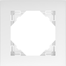

Frame - 1 gang LOGUS, AQUARELLA / plastic - metalic, ice
90910 TGE
Frame - 1 gang LOGUS, AQUARELLA / plastic - metalic, ice


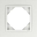
Frame - 1 gang LOGUS, CRYSTAL / glass hardened, ice
90910 TCG
Frame - 1 gang LOGUS, CRYSTAL / glass hardened, ice


No data available.
No data available.