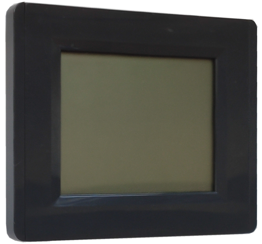
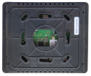
C-RC-0011R CIB, wall room controller, anthracite/anthraciteTXN 133 77.02
C-RC-0011R CIB, wall room controller, anthracite/anthracite
| DI | |
|---|---|
| DI/AI | |
| DO | |
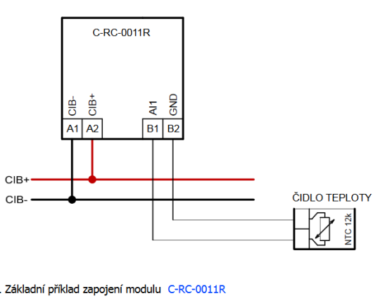
| AI | 1x AI for NTC 12k |
| AO | |
| COM | 1x CIB slave |
| SENSOR | Temperature Humidity 5x capacitive button |
| Picture | Variant | Variant description |
|---|---|---|

|
C-RC-0011R | |

|
C-RC-0011R CIB, wall room controller, anthracite/anthracite |
C-RC-0011R is a programmable interior wall controller for controlling heating (air conditioning), ventilation, etc. It allows you to set the heating time program throughout the week, change the heating mode, measure room temperature and humidity and measure the external temperature with an NTC sensor.
It is connected via the CIB Common Installation Bus® to the control unit, which can provide the module with additional measured values for display.
The display allows you to display 53 icons 1 main and 1 secondary value and their units. At the bottom of the display there are 5 capacitive buttons.
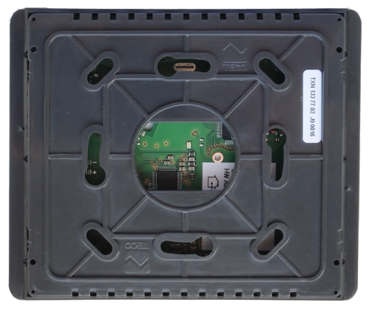
The module is designed for operation in a normal, chemically non-aggressive environment. It consists of two parts: the bottom and the cover with a printed circuit board, terminals and display. It is fixed with 2 or 4 screws to the installation box 60 mm diameter flush-mounted box or to the wall.
The module is designed as a standard unit on the CIB bus, integrated into the Mosaic environment.
| Order num. | TXN 133 77.02 |
|---|---|
| Teco code | TXN 133 77.02 |
| Categories | CFox - Teco, Touch control panels |
| Tags | - |
| COM - System buses | |
|---|---|
| CIB - Common Installation Bus (R): Installation I/O bus | 1x CIB slave |
| Parameter des Temperatursensors | |
| Temperature - Sensor type | SI 7020 |
| Temperature - Measurement range | 0°C ÷ 50°C |
| Temperature - Resolution | 0,1 °C |
| Temperature - Measurement accuracy | typ. ±0,4 °C |
| Humidity sensor parameters | |
| Relative humidity - Sensor type | SI 7020 |
| Relative humidity - Measurement range | 0 ÷ 100 %RH |
| Relative humidity - Resolution | 1 % RH |
| Power supply | |
| Supply voltage, tolerances | 24/27 V DC from CIB bus |
| Maximum power input | 0,15 W |
| Power supply from CIB - maximum current consumption (mA) | 10 mA |
| Power supply from CIB - Galvanic separation of power supply from internal circuits | No |
| Power supply from CIB - internal protection | No |
| Size and weight | |
| Weight approx. | 125 g |
| Product dimensions (width x height x depth) | 109 × 99 × 19,8 mm |
| Operating conditions, product standards | |
| Product standard | ČSN EN 60730-1 ed. 3:2012 (mod IEC 60730-1:2010) |
| Protection class of electrical object | III, according to ČSN EN 61140 ed.3: 2016 (idt IEC 61140:2016) |
| IP rating (Ingress Protection) according to ČSN EN 60529: 1993 (idt IEC 529: 1989) | IP10B |
| Operating areas | Normal, acc. ČSN 33 2000-1 ed.2: 2009 (mod IEC 60354-1:2005) |
| Degree of pollution | 1, according to ČSN EN 60664-1 ed.2:2008 ( idt IEC 60664-1:2007) |
| Overvoltage category installation | II, according to EN 60664-1 ed_2: 2008 (idt IEC 60641-1: 2007) |
| Type of device | On the wall |
| Working position | Vertical |
| Type of operation (operating frequency) | Continuous |
| Ambient operating temperatures | 0 °C to + 55 °C |
| Operating temperature minimum (° C) | 0°C |
| Operating relative humidity | from 10 % up to 95 % without condensation |
| Operating atmospheric pressure | min. 70 kPa (<3,000 m above sea level) |
| Storage temperatures | –25 °C to +70 °C |
| Electromagnetic compatibility, Mechanical endurance | |
| Electromagnetic compatibility / Emission | ČSN EN 55022 ed2:2007 (mod CISPR22:2005) |
| Electromagnetic compatibility / Immunity | min. according to ČSN EN 60730-1 ed.2: 2001 |
| Sinusoidal vibration endurance | 10 Hz to 57 Hz, amplitude 0,075 mm, 57 Hz to 150 Hz, acceleration 1 G (Fc test according to EN 60068-2-6: 1997 (idt IEC 68-2-6: 1995), 10 cycles per axis.) |
| Packaginng, transportation, storage | |
| Description | The module is packed in a paper box. This documentation is also part of the package. The outer packaging is carried out according to the scope of the order and the method of transport in a transport package provided with labels and other data necessary for transport. The product must not be exposed to direct weather conditions during transport and storage. Malting of the product is only allowed in clean rooms without conductive dust, aggressive gases and vapors. The most suitable storage temperature is 20 ° C |
| Installation | |
| Assembly description | Indoor wall mounting |
| Assembly description | The module is mounted in a vertical position on a standard installation box with a spacing of fixing screws of 60 mm or directly on the wall. Mounting holes are pre-molded in the bottom of the C-RC-0011R. The lower part should be screwed to the wall in a position where the inscription "LOWER" is legible. The lower part and the upper part (with display) are snapped in by latches, by slightly pressing the sides of the box and by light pulling both parts can be separated from each other. |
| Connection | |
| Connection of power and system communication | terminal block with screw terminal 1.5 mm2 |
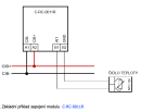
| Module connection | The module is implemented as a CIB bus module, which provides communication and power supply to the module. The CIB bus can have any topology and branching up to a distance of 500 m and up to 32 units on one CIB branch. The CIB bus master is the FOXTROT basic unit with an internal module or the external module CF-1141 with FW version 1.8 and higher. For more information, see the manual Peripheral modules on the CIB bus TXV 004 13. |
| Module operation | |
| Module configuration | The module is operated, set up and diagnosed from the Mosaic development environment. |
| Module diagnostics | The basic diagnostics is performed internally and the result is available in the relevant registers of the Mosaic environment. |
| Maintenance | |
| Description | The module does not require any maintenance under general installation conditions. |
| Notice | Because the module contains semiconductor components, it is necessary to follow the principles for working with electrostatic sensitive components when handling the removed cover. It is not allowed to directly touch the printed circuit boards without protective measures !!! |
| Warranty | |
| Generally | Warranty and complaint conditions are governed by the Terms and Conditions of Teco a.s. |
| Notice | You must meet all the conditions of this documentation before turning on the system. The system must not be put into service unless it has been verified and confirmed that the machinery meets the requirements of Directive 89/392 / EEC, in so far as it applies to it. Documentation subject to change. |
Files for designers
C-RC-0011R- Basic documentation
190.67 kB
Foxtrot 2 - library of elements in DXF and DWG formats, v. 2025/08.
21.80 MB
Foxtrot 2 - element library for SchemataCAD, v. 2025/08.
6.96 MB
User manuals
Peripheral module on CIB-Common Installation Bus(R) (cs), TXV00413_01
14.01 MB
Peripheral modules on the CIB Common Installation Bus(R) (en), TXV00413_02
13.94 MB, (EN, RU, DE, UA)
EC - Declaration of Conformity
Foxtrot 2 - EC Declaration of conformity (en)
590.59 kB, (EN, RU, DE, UA)
- C-RC-0011R - The C-RC-0011R interior control unit with an LCD display and 5 touch buttons is designed primarily for local control of heating, cooling and ventilation systems for office buildings, such as remote control for heating systems, etc. The disp...
- TCIB_CRC011R_ICO Structure - Hello, I have bought a C-RC-0011R device and I use it in Display only mode. I would like to load the Icon structure on the device but I didn't find the TCIB_CRC011R_ICO structure in the libraries. I made a structure with the same fields but it does...
- TCIB_CRC011R_ICO Structure - ...l. You can define the structure with the same name which is compiled conditionally. Then it doesn't depend if the module C-RC-0011R is added into the project. If yes, it will be used a structure defined in CONFIG.ST file. If no then it will be us...

