
C-RC-0002R-LOGUS, aluminum, TALTXN 133 33.LTAL
C-RC-0002R-Logus aluminum; CIB, Wall controller with LCD1, 3 buttons, temperature sensor
| DI | 3x Button |
|---|---|
| DI/AI | |
| DO | 1x green LED |
| AI | 1x AI |
| AO | |
| COM | 1x CIB slave 1x LCD display |
| SENSOR | 1x internal temperature |
| Picture | Variant | Variant description |
|---|---|---|

|
C-RC-0002R-Logus; white, TBR | Color: White |

|
C-RC-0002R-Logus, ivory, TMF | Color: Ivory |
|
|
C-RC-0002R-Logus; ice, TGE | Color: Ice |

|
C-RC-0002R-Logus; pearlescent, TPE | Color: Pearl |
|
|
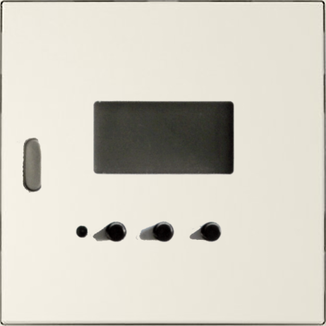
C-RC-0002R-LOGUS, aluminum, TAL | Color: Aluminum |

|
C-RC-0002R-LOGUS, gray, TIS | Color: Grey |

|
C-RC-0002R-Logus black | Color: Gold |

|
C-RC-0002R-Logus gold | Color: Black |
The C-RC-0002R module is an interior controller with a 3-digit 7-segment LCD display, 3 buttons and an LED for signaling. It is designed for wall mounting in an installation box to control the temperature in the room. It is connected in two wires to the CIB Common Installation Bus®.
It has two parts. The first part is visible, on the wall with control and display, the second part - a tube module - connected via a flat cable is placed in the installation box and is used to connect to the CIB bus.
The module also contains two measuring inputs. The first is permanently connected to the internal temperature sensor. The second input is led through the wires on the tube module and a separate external sensor can be connected to it.
| Order num. | TXN 133 33.LTAL |
|---|---|
| Teco code | TXN 133 33.LTAL |
| Categories | CFox - LOGUS, Covers and devices |
| Tags | - |
| COM - System buses | |
|---|---|
| CIB - Common Installation Bus (R): Installation I/O bus | 1x CIB slave |
| AI - Analog Input Ranges (Group A) | |
| Parameters valid for inputs on the terminals | +IN, -IN |
| Passive sensor | Resistance transmitter 0-100 kOhm |
| Passive sensor | NTC Thermistor 5k / 25 °C (–40 to + 125 °C) |
| Passive sensor | NTC Thermistor 10k / 25 °C (-40 to + 125 °C) |
| Passive sensor | NTC Thermistor 12k / 25 °C (-40 to + 125 °C) |
| Passive sensor | NTC Thermistor 15k / 25 °C (-40 to + 125 °C) |
| Passive sensor | NTC Thermistor 20k / 25 °C (-40 to + 125 °C) |
| Parameter des Temperatursensors | |
| Temperature - Description of measurements |
Main analog input = Internal sensor temperature Additional analog input = External sensor temperature (according to the sensor used) |
| Temperature - Sensor type | Pt1000 |
| Temperature - Measurement range | 0°C ÷ 50°C |
| Temperature - Resolution | 0,1 °C |
| Temperature - Measurement accuracy | typ. ±0,5 °C |
| Power supply | |
| Supply voltage, tolerances | 24/27 V DC from CIB bus |
| Maximum power input | < 0,5 W |
| Galvanic separation of power supply from internal circuits | No |
| Size and weight | |
| Weight approx. | 75 g |
| Product dimensions (width x height x depth) | 83 x 81 x 25 mm |
| Operating conditions, product standards | |
| Product standard | ČSN EN 60730-1 ed. 2:2001 (mod IEC 60730-1:1999) |
| Protection class of electrical object | III, according to ČSN EN 61140 ed.3: 2016 (idt IEC 61140:2016) |
| IP rating (Ingress Protection) according to ČSN EN 60529: 1993 (idt IEC 529: 1989) | IP20 |
| Operating areas | Normal, acc. ČSN 33 2000-1 ed.2: 2009 (mod IEC 60354-1:2005) |
| Degree of pollution | 1, according to ČSN EN 60664-1 ed.2:2008 ( idt IEC 60664-1:2007) |
| Overvoltage category installation | II, according to EN 60664-1 ed_2: 2008 (idt IEC 60641-1: 2007) |
| Type of device | In the installation box on the wall |
| Working position | Horizontal |
| Type of operation (operating frequency) | Continuous |
| Ambient operating temperatures | 0 °C to + 55 °C |
| Operating relative humidity | from 10 % up to 95 % without condensation |
| Operating atmospheric pressure | min. 70 kPa (<3,000 m above sea level) |
| Storage temperatures | –25 °C to +70 °C |
| Electromagnetic compatibility, Mechanical endurance | |
| Electromagnetic compatibility / Emission | B, according to EN 55022: 1999 (mod CISPR22: 1997) |
| Electromagnetic compatibility / Immunity | min. according to ČSN EN 60730-1 ed.2: 2001 |
| Sinusoidal vibration endurance | 10 Hz to 57 Hz, amplitude 0,075 mm, 57 Hz to 150 Hz, acceleration 1 G (Fc test according to EN 60068-2-6: 1997 (idt IEC 68-2-6: 1995), 10 cycles per axis.) |
| Packaginng, transportation, storage | |
| Description |
The module is packed in a paper box. This documentation is also part of the package. The outer packaging is carried out according to the scope of the order and the method of transport in a transport package provided with transport labels and other data necessary for transport. Transport from the manufacturer is carried out in the manner agreed upon when ordering. The transport of the product by the customer's own means must be carried out by covered means of transport, in the position specified by the label on the packaging. The box must be stored in such a way that it does not move spontaneously and the outer packaging is not damaged. The product must not be exposed to direct weather conditions during transport and storage. Transport is permitted at temperatures of -25 ° C to 70 ° C, relative humidity of 10% to 95% (non-condensing) and a minimum atmospheric pressure higher than 70 kPa. The product may only be stored in clean rooms free of conductive dust, aggressive gases and vapors. The most suitable storage temperature is 20 ° C. |
| Installation | |
| Assembly description | The sensor module is mounted in the installation box using a mounting fitting. When mounting and positioning the sensor module, it is necessary to ensure that the operating conditions are observed during its subsequent operation. |
| Connection | |
| Connection description |
The module is implemented as a standard unit on a two-wire CIB bus, which ensures communication and power supply of the entire sensor. The bus wires are connected to the wires that are routed on the tube module (for marking, see Fig. 1). The CIB bus can have any topology and branching up to a distance of 500 m and up to 32 units on one CIB branch. The CIB bus master is the basic PLC unit TECOMAT FOXTROT or an external CIB bus master, eg the CF-1141 module. Further information can be found in the manual Peripheral modules on the CIB TXV 004 13. |
| Connection of power and system communication | Ribbon flat conductors 0.15 / 0.5 mm2 |
| CIB connection | Conductors 0.5 mm2 |
| Module operation | |
| Module configuration |
SW configuration, operation and diagnostics of the C-RC-0002R module are performed from the MOSAIC programming environment. Notice: Improper connection of the terminals and setting of the jumpers may damage the module. |
| Commissioning | The module is operated, set and diagnosed from the MOSAIC programming environment or other parameterization software. The module is ready for operation after connecting the supply voltage and the CIB bus. The HW address is indicated on the label on the module. |
| Module diagnostics | The basic diagnostics is performed internally and the result is available in the relevant registers of the Mosaic environment. |
| Maintenance | |
| Description | The module does not require any maintenance under general installation conditions. The operations in which a part of the module has to be dismantled must always be carried out with the supply voltage disconnected. |
| Notice | Because the module contains semiconductor components, it is necessary to follow the principles for working with electrostatic sensitive components when handling the removed cover. It is not allowed to directly touch the printed circuit boards without protective measures !!! |
| Warranty | |
| Generally | Warranty and complaint conditions are governed by the Terms and Conditions of Teco a.s. |
| Notice | You must meet all the conditions of this documentation before turning on the system. The system must not be put into service unless it has been verified and confirmed that the machinery meets the requirements of Directive 89/392 / EEC, in so far as it applies to it. Documentation subject to change. |
HW documentation
C-RC-0002R - Basic documentation
407.91 kB
User manuals
Peripheral module on CIB-Common Installation Bus(R) (cs), TXV00413_01
14.01 MB
Peripheral modules on the CIB Common Installation Bus(R) (en), TXV00413_02
13.94 MB, (EN, RU, DE, UA)
Files for designers
Foxtrot 2 - library of elements in DXF and DWG formats, v. 2025/08.
21.80 MB
Foxtrot 2 - element library for SchemataCAD, v. 2025/08.
6.96 MB
EC - Declaration of Conformity
Foxtrot - EC Declaration of conformity
295.20 kB, (EN, RU, DE, UA)


Frame - 1 gang LOGUS, AQUARELLA / plastic - metalic, ice
90910 TGE
Frame - 1 gang LOGUS, AQUARELLA / plastic - metalic, ice


Frame - 1 gang LOGUS, CRYSTAL / glass hardened, ice
90910 TCG
Frame - 1 gang LOGUS, CRYSTAL / glass hardened, ice


No data available.
No data available.