


C-IT-0908S-PNP_kopie_55TXN 133 52.01
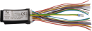
C-IT-0908S-NPN; CIB, 6xDI, 2xAI/DI, 1x AI (contact/temperature), 8x NPN LED driver 3mA (LED - common anode)
| DI | 6x DI |
|---|---|
| DI/AI | 2x DI/AI |
| DO | 8x DO |
| AI | 1x AI |
| AO | |
| COM | 1x CIB |
| SENSOR |
| Picture | Variant | Variant description |
|---|---|---|

|
C-IT-0908S-PNP_kopie_55 | |
|
|
C-IT-0908S-PNP |
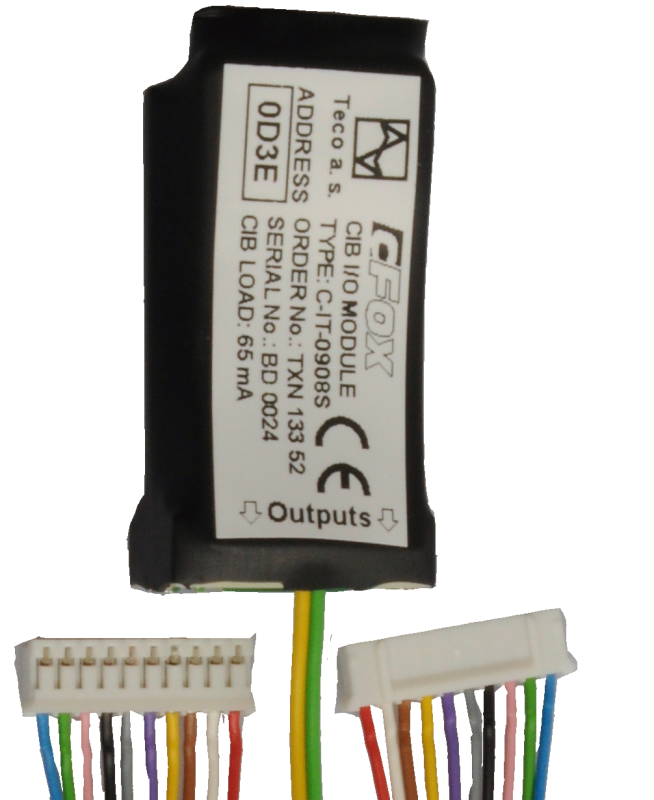
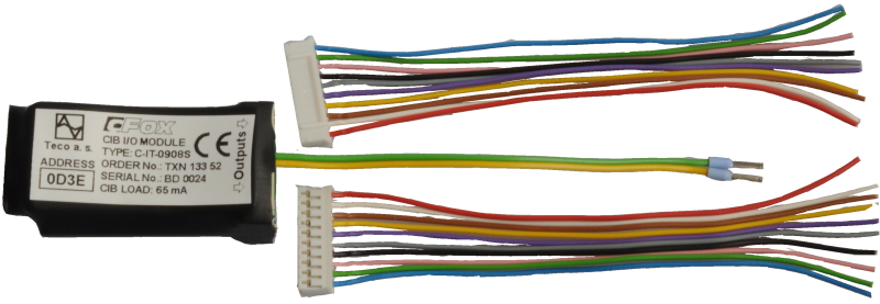
The C-IT-0908S module is intended for the CIB Common Installaton Bus® for the connection of sensing analog or binary signals (sensing potential-free contacts) and controlling binary outputs, including for driving LEDs.
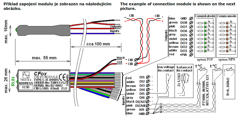
Inputs DI1 to DI6 can only be set as binary. They also work in balanced input mode.
Inputs DI / AI7 to DI / AI8 can be set as binary or analog.
Input AI9 can only be set as analog.
Eight binary outputs are designed to drive LEDs connected in a group with common cathodes or common anodes (version with * .01 number),
| Order num. | TXN 133 52.01 |
|---|---|
| Teco code | TXN 133 52.01 |
| Categories | CFox - Built-in modules |
| Tags | - |
| COM - System buses | |
|---|---|
| CIB - Common Installation Bus (R): Installation I/O bus | 1x CIB slave |
| DI - Organization of binary inputs | |
| Total number of binary inputs | 8 |
| Number of groups of binary inputs | 2 |
| Organization of binary inputs into groups | 6x (DI1 - DI6); 2x (DI/AI7 a DI/AI8) |
| DI - Parameters of binary inputs DC (group A) | |
| Number of inputs in group | 6 |
| Common wire | GND - module ground |
| Combined input type | DI - Binary, balanced |
| Galvanic separation of inputs from CIB bus | No |
| Max. measuring voltage on the connected contact | 3,3 V DC |
| Internal input resistance | 2,2 kΩ |
| Balanced resistance input | 2× 1k1 (tamper/0/1/tamper) |
| DO/RO - Organization of binary outputs | |
| Total number of binary outputs | 8 |
| Number of binary output groups | 1 |
| DO - Parameters of binary transistor outputs (group A) | |
| Number of transistor outputs | 8 |
| Number of output groups | 1 |
| Number of outputs in group | 8 |
| Output type | PNP open collector (variant with number .01: NPN) |
| Galvanic separation from internal circuits | No |
| Switching voltage | 27 V DC |
| Switching current, output load | 3mA max. |
| AI - Organization of analog inputs | |
| Total number of analog inputs | 3 |
| Number of analog input groups | 2 |
| Organization of analog inputs into groups | (DI/AI7, DI/AI8) + AI9 |
| Input type | With common clamp |
| Common wire | GND terminal |
| Galvanic separation from internal circuits | No |
| Diagnostics | overload signaling in status word |
| AI - Analog Input Ranges (Group A) | |
| Passive sensor | Pt1000, W100 = 1,385 (-90 to +320 °C) |
| Passive sensor | Pt1000, W100 = 1,391 (-90 to +320 °C) |
| Passive sensor | Ni1000, W100 = 1,500 (–60 to +200 ° C) |
| Passive sensor | Ni1000, W100 = 1.617 (-60 to +200 ° C) |
| Passive sensor | Resistance transmitter 0-160 kOhm |
| Passive sensor | KTY81-121; PTC thermistor (-55 to + 125 °C) |
| Passive sensor | NTC Thermistor 12k / 25 °C (-40 to + 125 °C) |
| Resistance measurement error - maximum error at 25 ° C | ± 0.5% of full scale |
| Power supply | |
| Supply voltage, tolerances | 24/27 V DC from CIB bus |
| Power supply from CIB - typical current consumption (mA) | 30 mA |
| Power supply from CIB - maximum current consumption (mA) | 65 mA |
| Power supply from CIB - internal protection | No |
| Size and weight | |
| Weight approx. | 7 g |
| Module width | 55 mm |
| Module height | 26 mm |
| Module depth | 20 mm |
| Product dimensions (width x height x depth) | 55 × 26 × 20 mm |
| Operating conditions, product standards | |
| Product standard | ČSN EN 60730-1 ed. 2:2001 (mod IEC 60730-1:1999) |
| Protection class of electrical object | III, according to ČSN EN 61140: 2003 (idt IEC 61140: 2001) |
| IP rating (Ingress Protection) according to ČSN EN 60529: 1993 (idt IEC 529: 1989) | IP10B |
| Operating areas | Normal, according to ČSN 33 2000-3: 1995 (mod IEC 364-3: 1993) |
| Degree of pollution | 1, according to ČSN EN 60664-1: 2004 (mod IEC 60664-1: 1992) |
| Overvoltage category installation | II, acc. ČSN EN 60664-1:2004 (mod IEC 606641:1992) |
| Type of device | In the installation box, under the cover |
| Working position | Any |
| Type of operation (operating frequency) | Continuous |
| Ambient operating temperatures | 0 ° C to + 70 ° C |
| Operating temperature maximum (° C) | +70°C |
| Operating temperature minimum (° C) | 0°C |
| Operating relative humidity | from 10 % up to 95 % without condensation |
| Operating atmospheric pressure | min. 70 kPa (<3,000 m above sea level) |
| Storage temperatures | –25 ° C to + 85 ° C |
| Electromagnetic compatibility, Mechanical endurance | |
| Electromagnetic compatibility / Emission | ČSN EN 55022 ed2:2007 (mod CISPR22:2005) |
| Electromagnetic compatibility / Immunity | min. according to ČSN EN 60730-1 ed.2: 2001 |
| Sinusoidal vibration endurance | 10 Hz to 57 Hz, amplitude 0,075 mm, 57 Hz to 150 Hz, acceleration 1 G (Fc test according to EN 60068-2-6: 1997 (idt IEC 68-2-6: 1995), 10 cycles per axis.) |
| Packaginng, transportation, storage | |
| Description | Модуль упакован в антистатический пакет. Эта документация также является частью пакета. Внешняя упаковка осуществляется в соответствии с объемом заказа и способом транспортировки в транспортной упаковке, снабженной этикетками и другими данными, необходимыми для транспортировки. Продукт не должен подвергаться воздействию прямых погодных условий во время транспортировки и хранения. Соложение продукта разрешено только в чистых помещениях. без токопроводящей пыли, агрессивных газов и паров. Наиболее подходящая температура хранения - 20 ° C. |
| Installation | |
| Assembly description | The module C-DM-0001B-SL is mounted in arbitrary positioninto instalation box under a lid or under device located in box. |
| Connection | |
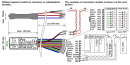
| Connection of power and system communication | Ribbon flat conductors 0.15 / 0.5 mm2 |
| Connection of inputs / outputs | Strip wires 0.15 / 0.5 mm2 |
| Module operation | |
| Commissioning | The module is operated, set and diagnosed from the MOSAIC programming environment or other parameterization software. The module is ready for operation after connecting the supply voltage and the CIB bus. The HW address is indicated on the label on the module. |
| Module diagnostics | The basic diagnostics is performed internally and the result is available in the relevant registers of the Mosaic environment. |
| Maintenance | |
| Description | The module does not require any maintenance under general installation conditions. |
| Notice | Because the module contains semiconductor components, it is necessary to follow the principles for working with electrostatic sensitive components when handling the removed cover. It is not allowed to directly touch the printed circuit boards without protective measures !!! |
| Warranty | |
| Generally | Warranty and complaint conditions are governed by the Terms and Conditions of Teco a.s. |
| Notice | You must meet all the conditions of this documentation before turning on the system. The system must not be put into service unless it has been verified and confirmed that the machinery meets the requirements of Directive 89/392 / EEC, in so far as it applies to it. Documentation subject to change. |
HW documentation
C-IT-0908S - Basic documentation
1.10 MB, (EN)
User manuals
Peripheral module on CIB-Common Installation Bus(R) (cs), TXV00413_01
14.01 MB
Peripheral modules on the CIB Common Installation Bus(R) (en), TXV00413_02
13.94 MB, (EN, RU, DE, UA)
Files for designers
Foxtrot 2 - library of elements in DXF and DWG formats, v. 2025/08.
21.80 MB
Foxtrot 2 - element library for SchemataCAD, v. 2025/08.
6.96 MB
EC - Declaration of Conformity
Foxtrot - EC Declaration of conformity
295.20 kB, (EN, RU, DE, UA)
- C-IT-0908S - The C-IT-0908S module (order. no.: The TXN 133 52) and its variant with a reversed outputs polarity, the C-IT-0908S-NPN (TXN 133 52.01), are designed to connect analogue or digital input signals and to control output binary signals for energizing LE...
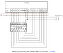
- The JUNG 3248TSM controller scanned by the C-IT-0908S input module - ...h nominal 24 VAC/DC power supply), and eight LEDs (24 VDC, 1 mA power supply). It can be connected to the embedded module C-IT-0908S (the PNP version - order No. TXN 133 52), which should be placed in the flush-box under the controller, which m...
- The short-stroke push-buttons S-WS-0004R-Merten, connection to the C-IT-0504S - ...R-Merten can also be connected to different inputs and outputs while maintaining the polarity of the inputs and outputs. The C-IT-0908S-PNP module may also be used, but approx. 3k3 resistors must be included in series with the binary outputs of the C...
- Control push-buttons on the wall (control of lighting, blinds, etc.) - Control units on the wall (a replacement of conventional switches) can be designed or integrated into the system in several ways, depending on the comfort, options, price and assortment. The first one is a controller as the bus element of...
No data available.