


C-IS-0404STXN 143 14TXN 143 14
C-IS-0404S; CIB, 4x AI/DI, 4x DO (1/2 H-bridge / PWM open collector)
| DI | |
|---|---|
| DI/AI | 4x DI/AI |
| DO | |
| AI | |
| AO | |
| COM | |
| SENSOR |
| Picture | Variant | Variant description |
|---|---|---|

|
C-IS-0404STXN 143 14 | |

|
C-IS-0404S |
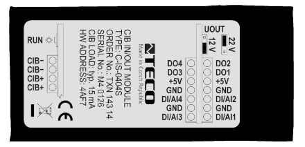
The C-IS-0404S module on the CIB Common Installation Bus® with 4x AI / DI and 4x DO and is built-in. It contains four binary outputs that can be used (in pairs DO1 with DO2 and DO3 with DO4) as 'H bridges' for controlled polarity reversal or as PWM outputs of the open collector type eg for control of model actuators (only with external power supply), or as common transistor outputs 24 VDC 50 mA.
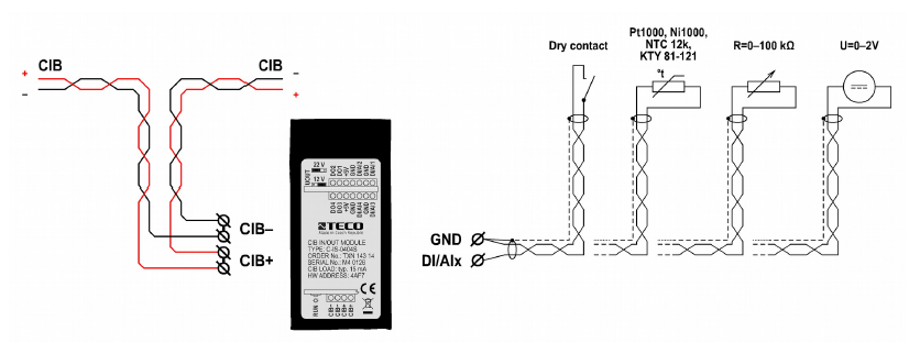
It contains four universal inputs configurable in pairs (DI / AI1 with DI / AI2 and DI / AI3 with DI / AI4) either as binary allowing connection of a potential-free contact against a common GND conductor or as analog for direct connection of passive resistance sensors Pt1000, Ni1000, NTC 12k , KTY 81-121 (measured resistance value is converted in the module directly to a numerical temperature value), or general resistance measurement in the range of 0–100 kΩ or DC voltage in the range of 0–2 V.
The TXN 143 14 module is in a shrink tube and is equipped with terminal blocks with tongue terminals.
The TXN 143 14.01 module is not protected by a tube or does not contain terminal blocks, all signals are routed to the socket strips, a built-in connection is assumed here by sliding the module onto the plugs of the expansion board.
| Order num. | TXN 143 14 |
|---|---|
| Teco code | TXN 143 14 |
| Categories | CFox - Built-in modules |
| Tags | - |
| COM - System buses | |
|---|---|
| CIB - Common Installation Bus (R): Installation I/O bus | 1x CIB slave |
| DI - Organization of binary inputs | |
| Total number of binary inputs | 4 |
| Number of groups of binary inputs | 2 |
| Organization of binary inputs into groups | 2x (DI1, DO2) 2x (DI3, DI4) |
| DI - Parameters of binary inputs DC (group A) | |
| Common wire | GND - module ground |
| Combined input type | DI/AI Active, for sensing potential-free contacts and measuring resistance sensors |
| Galvanic isolation of inputs from internal/peripheral circuits | No |
| Diagnostics | signaling of excited input in Mosaic |
| DO/RO - Organization of binary outputs | |
| Total number of binary outputs | 4 |
| Number of binary output groups | 2 |
| DO - Parameters of binary transistor outputs (group A) | |
| Parameters valid for the terminals | DO1 - DO4 |
| Number of transistor outputs | 4 |
| Number of output groups | 2 |
| Number of outputs in group | 2 |
| Organization of transistor outputs into groups | 2x (DO1, DO2) 2x (DO3, DO4) |
| Switching voltage | 20 V DC |
| Switching current, output load | 40 mA max. (sum of currents of all DO) |
| Short circuit protection | Yes |
| Special functions (A) | PWM |
| Operating frequency | 50 Hz max. |
| Alternation settings | 0 – 100 % |
| AI - Organization of analog inputs | |
| Total number of analog inputs | 4 |
| Number of analog input groups | 2 |
| Organization of analog inputs into groups | 2x AI (AI1, AI2) 2x AI (AI3, AI4) |
| Common wire | GND terminal |
| Galvanic separation from internal circuits | No |
| Converter type | Approximation |
| Operating modes | periodic input sensing |
| Analog input error - Temperature coefficient | ± 0,1% of full scale/K |
| Analog input error - Nonlinearity | ± 0,1% of full scale |
| Analog input error - Steady state repeatability | ± 0,5% of full scale |
| AI - Analog Input Ranges (Group A) | |
| Parameters valid for inputs on the terminals | AI1 - AI4 |
| Voltage | 0 to 2 V / 805.9 μV |
| Voltage input error - max. error at 25 ° C | ± 2.0% of full scale |
| Voltage input error - temperature coefficient | ± 0,05% of full scale/K |
| Voltage input error - non-linearity | ± 0.1% of full scale |
| Voltage input error - repeatability under steady state conditions | 0.5% of full scale |
| Passive sensor | Pt1000, W100 = 1,385 (-90 to +320 °C) |
| Passive sensor | Pt1000, W100 = 1,391 (-90 to +320 °C) |
| Passive sensor | Ni1000, W100 = 1,500 (–60 to +200 ° C) |
| Passive sensor | Ni1000, W100 = 1.617 (-60 to +200 ° C) |
| Passive sensor | Resistance transmitter 0-100 kOhm |
| Passive sensor | KTY81-121; PTC thermistor (-55 to + 125 °C) |
| Passive sensor | NTC Thermistor 12k / 25 °C (-40 to + 125 °C) |
| DI: Voltage-free contact | 0 when> 1.5 kOhm, 1 when <0.5 kOhm |
| DI: Balanced resistance input | 2x 1k1 (tamper/0/1/tamper) |
| Resistance measurement error - maximum error at 25 ° C | ± 0.5% of full scale |
| Resistance measurement error - temperature coefficient | ± 0.05% of full scale / K |
| Resistance measurement error - non-linearity | ± 0.09% of full scale |
| Resistance measurement error - repeatability at steady conditions | 0.07% of full scale |
| Power supply | |
| Nominal supply voltage (V) | 24 V DC |
| Power supply from CIB - typical current consumption (mA) | 50 mA |
| Power supply from CIB - maximum current consumption (mA) | 60 mA |
| Galvanic separation of power supply from internal circuits | No |
| Size and weight | |
| Weight approx. | 50 g |
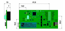
| Module width | 80 mm |
| Module height | 40 mm |
| Module depth | 15 mm |
| Product dimensions (width x height x depth) | 80 x 40 x 15 mm |
| Operating conditions, product standards | |
| Product standard | ČSN EN 60730-1 ed.4 :2017 (EN 60730-1:2016) -Automatic electronic control device (for household and similar purposes) |
| Protection class of electrical object | II, according to ČSN EN 61140 ed.3: 2016 (idt IEC 61140:2016) |
| IP rating (Ingress Protection) according to ČSN EN 60529: 1993 (idt IEC 529: 1989) | IP10 |
| Operating areas | Normal, acc. ČSN 33 2000-1 ed.2: 2009 (mod IEC 60354-1:2005) |
| Degree of pollution | 2, according to ČSN EN 60664-1 ed.2: 2008 (idt IEC 60664-1: 2007) |
| Overvoltage category installation | III, according to EN 60664-1 ed_2: 2008 (idt IEC 60641-1: 2007) |
| Type of device | In the installation box, under the cover |
| Working position | Any |
| Type of operation (operating frequency) | Continuous |
| Ambient operating temperatures | -20 °C to + 55 °C |
| Operating temperature maximum (° C) | +55°C |
| Operating temperature minimum (° C) | -20°C |
| Operating relative humidity | from 10 % up to 95 % without condensation |
| Operating atmospheric pressure | min. 70 kPa (<3,000 m above sea level) |
| Storage temperatures | –25 °C to +70 °C |
| Electromagnetic compatibility, Mechanical endurance | |
| Electromagnetic compatibility / Emission | A, according to EN 55032 ed. 2: 2017 (idt CISPR 32: 2015) |
| Electromagnetic compatibility / Immunity | min. according to ČSN EN 60730-1 ed.3: 2012 |
| Sinusoidal vibration endurance | 10 Hz to 57 Hz, amplitude 0,075 mm, 57 Hz to 150 Hz, acceleration 1 G (Fc test according to EN 60068-2-6: 1997 (idt IEC 68-2-6: 1995), 10 cycles per axis.) |
| Installation | |
| Attention! | The modules contain components sensitive to electrostatic charge, so we observe them principles for working with these circuits! We handle only on the module disconnected from the power supply! When replacing the submodules, the correctness of the deployment must be carefully checked of the submodule cavities against the tips on the motherboard. The tubes have no coding position and incorrect installation, may occur when the power is turned on again damage to the submodule or even the motherboard !!! |
| Connection | |
| Cross-section of connected wires fixed (min) | 0,14 mm2 |
| Cross-section of connected wires fixed (max) | 0,5 mm2 |
| Cross-section of connected wires stranded (min) | 0,14 mm2 |
| Cross-section of connected wires stranded (max) | 0,25 mm2 |
| Module operation | |
| Module configuration | The module is operated, set up and diagnosed from the Mosaic development environment. |
| Module diagnostics | The basic diagnostic system of the module is a part of its standard software. It operates from module power on and operates independently of the user. Diagnostic error states of the module and connected peripheral modules of the assembly are signaled |
| Maintenance | |
| Description | The module does not require any maintenance under general installation conditions. |
| Notice | Because the module contains semiconductor components, it is necessary to follow the principles for working with electrostatic sensitive components when handling the removed cover. It is not allowed to directly touch the printed circuit boards without protective measures !!! |
| Warranty | |
| Generally | Warranty and complaint conditions are governed by the Terms and Conditions of Teco a.s. |
| Notice | You must meet all the conditions of this documentation before turning on the system. The system must not be put into service unless it has been verified and confirmed that the machinery meets the requirements of Directive 89/392 / EEC, in so far as it applies to it. Documentation subject to change. |
HW documentation
C-IS-0404S - Basic documentation
688.83 kB, (EN)
User manuals
Peripheral module on CIB-Common Installation Bus(R) (cs), TXV00413_01
14.01 MB
Peripheral modules on the CIB Common Installation Bus(R) (en), TXV00413_02
13.94 MB, (EN, RU, DE, UA)
EC - Declaration of Conformity
Foxtrot - EC Declaration of conformity
295.20 kB, (EN, RU, DE, UA)
Files for designers
Foxtrot 2 - library of elements in DXF and DWG formats, v. 2025/08.
21.80 MB
Foxtrot 2 - element library for SchemataCAD, v. 2025/08.
6.96 MB
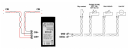
- Control of 3 SSRs (water heating) using the C-IS-0404S module - For direct control of SSRs (control based on mains cycles, zero-crossing switching), we can use the C-IS-0404S module. For SSRs with a maximum current consumption of 13 mA and a switching voltage of 4 V—such as the RGS1A23D25 used here&mdash...
- Model servo control by module C-IS-0404S - Up to 4 model servos can be controlled by the C-IS-0404S . module. Its outputs in the 50 Hz mode are used. Fig. 1 shows an example of connection of two servos, analogously the other 2 outputs are connected. Due to the power input of the motors, it...
- C-IS-0404S - C-IS-0404S is a module in a miniature built-in design with 4x DO and 4x AI / DI. It is connected to the master system via the CIB bus. It contains four binary outputs that can be used (in pairs DO1 with DO2 and DO3 with DO4) as 'H bridges'...
No data available.