


C-DM-0402M-RLCTXN 133 58
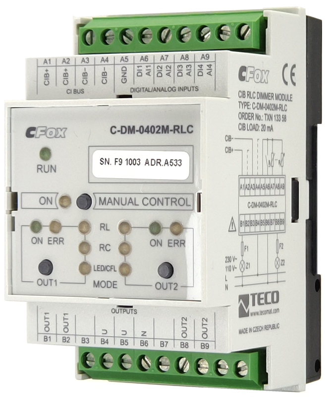
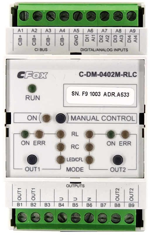
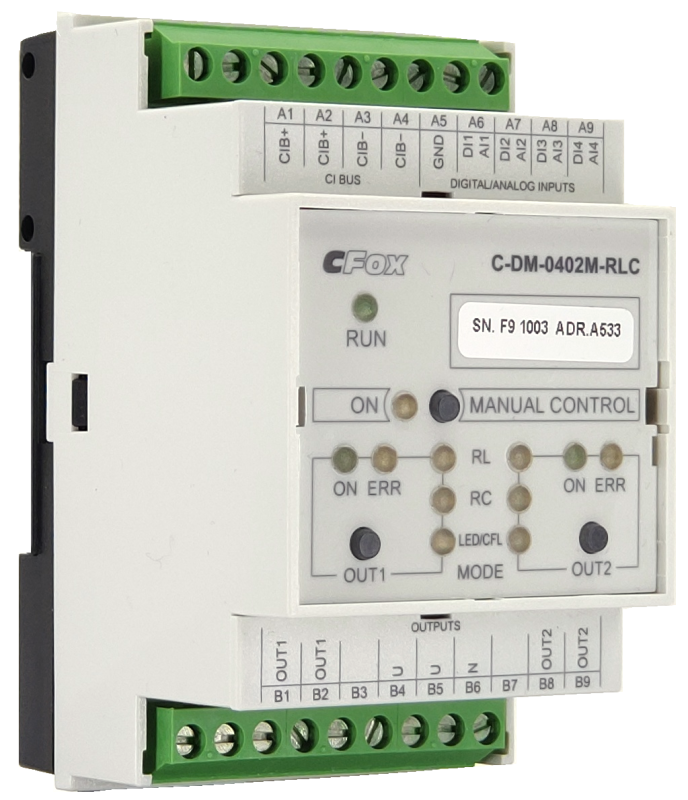
C-DM-0402M-RLC; CIB, 2x dimmer RLC, 230V AC, 2x 500W, 4x DI / AI
| DI | |
|---|---|
| DI/AI | 4x DI/AI |
| DO | 2x phase dimmer (230/115 VAC) |
| AI | |
| AO | |
| COM | 1x CIB slave |
| SENSOR |
| Picture | Variant | Variant description |
|---|---|---|

|
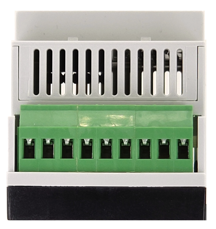
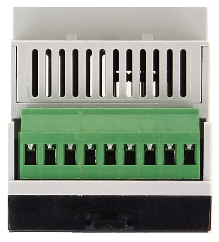
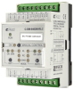
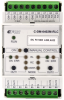
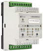
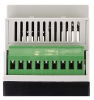
C-DM-0402M-RLC |
The C-DM-0402M-RLC module is a 2-channel dimmer for phase control of the intensity of light sources with a resistive, inductive or capacitive character. It is possible to control a load of 2x 500 VA in a 230 V AC / 50 Hz network or a load of 2x 250 VA in a 115 V AC / 60 Hz network.
The outputs can be interconnected and in a 230 V AC network the controlled load can be doubled to 1000 VA or even to 2000 VA by connecting all outputs on two modules and their coupled control via the CIB bus. In a 115 V A network, these maximum loads are adequately halved.
The module contains four universal AI / DI inputs allowing to connect temperature sensors or binary inputs for sensing contacts.
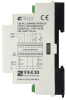
The module is designed for a DIN rail switchboard and is connected to the basic module via a two-wire CIB Common Installation Bus®.
The outputs can be interconnected and in a 230 V AC network the controlled load can be doubled to 1000 VA or even to 2000 VA by connecting all outputs on two modules and their coupled control via the CIB bus. In a 115 V A network, these maximum loads are adequately halved.
The module contains four universal AI / DI inputs allowing to connect temperature sensors or binary inputs for sensing contacts.
The module is designed for a DIN rail switchboard and is connected to the basic module via a two-wire CIB Common Installation Bus®.
| Order num. | TXN 133 58 |
|---|---|
| Teco code | TXN 133 58 |
| Categories | CFox - Modules on DIN rail |
| Tags | - |
| COM - System buses | |
|---|---|
| CIB - Common Installation Bus (R): Installation I/O bus | 1x CIB slave |
| DO/RO - Organization of binary outputs | |
| Total number of binary outputs | 2 |
| Number of binary output groups | 1 |
| DO - Parameters of binary transistor outputs (group A) | |
| Number of transistor outputs | 2 |
| Number of output groups | 1 |
| Number of outputs in group | 2 |
| Output type | MOSFET (Low-side switch) |
| Galvanic separation from internal circuits | Yes |
| Diagnostics | indication of energized output by LED on module panel |
| Power supply | |
| Module thermal/power loss | 5 W |
| Size and weight | |
| Weight approx. | 125 g |
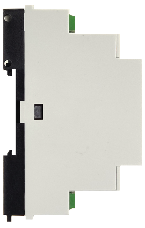
| Product dimensions (width x height x depth) | 52 x 90 x 58 mm |
| Operating conditions, product standards | |
| Product standard | ČSN EN 60730-1 ed.4 :2017 (EN 60730-1:2016) -Automatic electronic control device (for household and similar purposes) |
| Protection class of electrical object | II, according to ČSN EN 61140 ed.3: 2016 (idt IEC 61140:2016) |
| IP rating (Ingress Protection) according to ČSN EN 60529: 1993 (idt IEC 529: 1989) | IP20 |
| Operating areas | Normal, acc. ČSN 33 2000-1 ed.2: 2009 (mod IEC 60354-1:2005) |
| Degree of pollution | 1, according to ČSN EN 60664-1 ed.2:2008 ( idt IEC 60664-1:2007) |
| Overvoltage category installation | II, according to EN 60664-1 ed_2: 2008 (idt IEC 60641-1: 2007) |
| Type of device | Module on DIN rail |
| Working position | Vertical |
| Type of operation (operating frequency) | Continuous |
| Ambient operating temperatures | 0 ° C to + 55 ° C |
| Operating relative humidity | from 10 % up to 95 % without condensation |
| Operating atmospheric pressure | min. 70 kPa (<3,000 m above sea level) |
| Storage temperatures | –25 °C to +70 °C |
| Electromagnetic compatibility, Mechanical endurance | |
| Electromagnetic compatibility / Emission | B, according to EN 55032 ed. 2: 2017 (idt CISPR 32: 2015) |
| Electromagnetic compatibility / Immunity | min. according to ČSN EN 60730-1 ed.3: 2012 |
| Sinusoidal vibration endurance | 10 Hz to 57 Hz, amplitude 0,075 mm, 57 Hz to 150 Hz, acceleration 1 G (Fc test according to EN 60068-2-6: 1997 (idt IEC 68-2-6: 1995), 10 cycles per axis.) |
| Packaginng, transportation, storage | |
| Description | The module is packed in a paper box. This documentation is also part of the package. The outer packaging is carried out according to the scope of the order and the method of transport in a transport package provided with labels and other data necessary for transport. The product must not be exposed to direct weather conditions during transport and storage. Malting of the product is only allowed in clean rooms without conductive dust, aggressive gases and vapors. The most suitable storage temperature is 20 ° C |
| Installation | |
| Assembly description | The module is mounted in a vertical position on the U-rail ČSN EN 50022. Installation of the assembly (basic module and possibly peripheral modules) is performed according to TXV 004 13. |
| Connection | |
| Connection of power and system communication | connector with 2.5 mm2 screw terminal |
| Connection of inputs / outputs | connector with screw terminal 2.5 mm2 |
| Module installation tools | (-) 3 mm, flat screwdriver |
| Maintenance | |
| Description | The module does not require any maintenance under general installation conditions. The operations in which a part of the module has to be dismantled must always be carried out with the supply voltage disconnected. |
| Notice | Because the module contains semiconductor components, it is necessary to follow the principles for working with electrostatic sensitive components when handling the removed cover. It is not allowed to directly touch the printed circuit boards without protective measures !!! |
| Warranty | |
| Generally | Warranty and complaint conditions are governed by the Terms and Conditions of Teco a.s. |
| Notice | You must meet all the conditions of this documentation before turning on the system. The system must not be put into service unless it has been verified and confirmed that the machinery meets the requirements of Directive 89/392 / EEC, in so far as it applies to it. Documentation subject to change. |
HW documentation
C-DM-0402M-RLC - Basic documentation
968.40 kB, (EN)
User manuals
Peripheral module on CIB-Common Installation Bus(R) (cs), TXV00413_01
14.01 MB
Peripheral modules on the CIB Common Installation Bus(R) (en), TXV00413_02
13.94 MB, (EN, RU, DE, UA)
Files for designers
Foxtrot 2 - library of elements in DXF and DWG formats, v. 2025/08.
21.80 MB
Foxtrot 2 - element library for SchemataCAD, v. 2025/08.
6.96 MB
EC - Declaration of Conformity
Foxtrot - EC Declaration of conformity
295.20 kB, (EN, RU, DE, UA)
- C-DM-0402M-RLC - The C-DM-0402M-RLC is a dimming module for the CIB bus, fitted with 4 inputs and 2 outputs. The outputs are two independently phase-controlled and managed 230 VAC channels, each for loads up to 500VA. The dimmer and its control algorithm is designed...
- Power dissipation of modules for calculation of switchboard heating - ...55 C-BS-0001M; CIB bus separator, 1A C-BS-0001M 1,0 W TXN 133 58 C-DM-0402M-RLC; CIB, 2x dimmer RLC, 230V AC, 2x 500W, 4x DI/AI C-DM-0402M-RLC 5,0 W...
- Dimming - LV sources with wound and electronic transformers - The dimming module C-DM-0402M-RLC in DIN rail design can be used for dimming LV bulbs powered by wound or electronic transformers. Allows switching and dimming of RLC loads (resistive, inductive and capacitive loads) and dimmable compact LED sou...
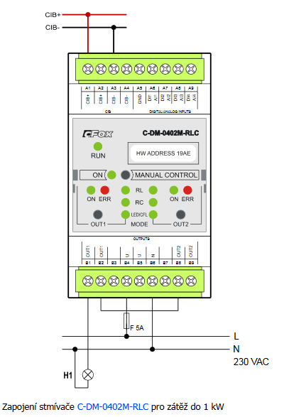
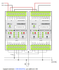
- Dimming of light bulbs up to 2 kW - ...he case of a parallel connection of 2 channels, we obtain a total dimming power of 1 kW, when connecting 4 channels (two C-DM-0402M-RLC modules) we get up to 2 kW. For correct operation, both modules (output connected for 2 kW output) mu...
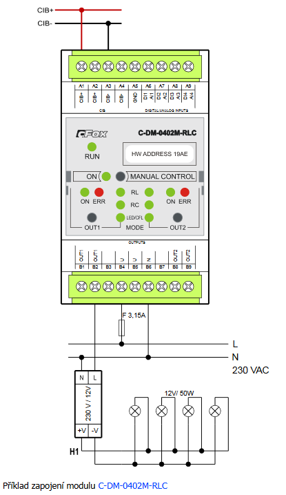
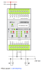
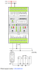
- Dimming of light bulbs with power input up to 500 W - The connection of the output and input circuits of the C-DM-0402M-RLC dimmer for loads up to 500 W is shown in the following figure. Fig. 1 Wiring example C-DM-0402M-RLC Notes: Inputs AI / DI1 to AI / DI4 are configurable...
- Dimming - bulbs, LED bulbs, CFL, 12 V sources - ...aving fluorescent lamps (CFL), electronic and wound transformers for 12 V sources (halogen bulbs), we have a dimming module C-DM-0402M-RLC available in DIN rail design. The C-DM-0402M-RLC module enables switching and dimming of...
- Continuous power control el. TV heating, SSR module - ...ore precise control of the power to the resistive load (max. 1 kW, possibly also 2 kW) will also enable the use of the C-DM-0402M-RLC module. When installing SSR modules, it is necessary to take into account their large own hea...
- Continuous power control el. heating, phase control of resistive load - ...up to a resistive load up to 1000 W (it is possible to expand up to 2000 W) we can use a standard peripheral module of the C-DM-0402M-RLC system primarily designed for dimming bulbs, wiring example and other information are given in this article...
- Dimming compact fluorescent lamps (CFL) and LED bulbs - Compact fluorescent lamps (further CFL) and LED bulbs (further LED), which are designed by the manufacturer for dimming, so they have the word "Dimmable" or an appropriate symbol on the cover, such as: are dimmed by the C-DM-0402M -RLC...
No data available.