


IT-8601TXN 186 01
IT-8601; 8x AI: 16 bit, differential, 0-10 V, 4-20 mA, RTD; GO
| DI | |
|---|---|
| DI/AI | |
| DO | |
| AI | 8x AI |
| AO | |
| COM | 1x TCL3 slave |
| SENSOR |
| Picture | Variant | Variant description |
|---|---|---|

|
IT-8601 |
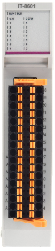
IT-8601 - expansion module, contains 8 analog inputs. The inputs are universal, independently configurable as voltage, current or for four-wire measurement of passive resistance sensors. Current inputs are jumper adjustable. The resolution is 24 bits, the module ensures the processing of the measured value, conversion to engineering units, etc. The analog inputs are galvanically separated from the internal circuits. The state of each input is diagnosed and signaled by an LED on the front panel of the module. The module is equipped with a screwless connector.
| Order num. | TXN 186 01 |
|---|---|
| Teco code | TXN 186 01 |
| Categories | TC800 - I / O expansion modules |
| Tags | - |
| COM - System buses | |
|---|---|
| TCL3 - system I/O bus | 1x TCL3 slave |
| AI - Organization of analog inputs | |
| Total number of analog inputs | 8 |
| Number of inputs per group | 8 |
| Number of analog input groups | 1 |
| Organization of analog inputs into groups | 8x AI (AI0-AI7) |
| Common wire | Minus |
| Galvanic separation from internal circuits | Yes, 8 inputs together |
| Diagnostics | yes, signaling on the module panel and in status |
| Type of protection | integrated overvoltage protections |
| External power supply | No |
| Digital resolution | 24 bit (ENOB: 18) |
| Converter type | sigma-delta |
| Filtration | low pass filter, digital comb filter 50/60 Hz |
| Internal calibration | auto-calibration every time the module is switched on |
| AI - Analog Input Ranges (Group A) | |
| Voltage | 0 to 10 V / 0.84 µV |
| Voltage | 0 to 5 V / 0.42 µV |
| Voltage | 0 to 2 V / 0,21 µV |
| Voltage | 0 to 1 V / 0,08 µV |
| Voltage | 0 to 0,5 V / 0,04 µV |
| Input impedance in the voltage signal range | > 100 kΩ (ranges 0.5 V, 1 V); > 50 kΩ (2 V, 5 V and 10 V ranges |
| Voltage input error - max. error at 25 ° C | ± 0.3% of full scale |
| Voltage input error - temperature coefficient | ± 0.02% of full scale / K |
| Voltage input error - non-linearity | ± 0.08% of full scale |
| Voltage input error - repeatability under steady state conditions | 0.05% of full scale |
| Permissible continuous overload - voltage input | ±60V maintaining accuracy, ±100V/1000h: 0.2% accuracy reduction, ±140V/1000h: 0.45% accuracy reduction |
| Total time of input transfer to system (TAID-TAIT) | type. 80 ms |
| Sample repetition time | type. 320 ms |
| Overload signaling | in the status word and LED on the front panel |
| Open input detection | No |
| Ccurrent | 0 to 20 mA / 0.002 µA |
| Current | 4 to 20 mA / 0.002 µA |
| Input impedance in the current signal range | 100 Ω |
| Current input error - maximum error at 25 ° C | ±0.55% of full scale |
| Error current input - temperature coefficient | ± 0.03% of full scale / K |
| Error current input - nonlinearity | ± 0.07% of full scale |
| Error current input - repeatability at steady-state conditions | 0.05% of full scale |
| Permissible continuous overload - current input, resistance 100 R | +30 mA (each terminal AIn_P, AIn_N against AGND) |
| Total time of input transfer to system (TAID-TAIT) | type. 80 ms |
| Sample repetition time | type. 320 ms |
| Overload signaling | in the status word and LED on the front panel |
| Open input detection | Yes, in status word (under-range - only 4 - 20 mA range) |
| Passive sensor | Pt100, W100=1,385 (-90 to +400 °C) |
| Passive sensor | Pt100, W100 = 1,391 (-90 to +400 °C) |
| Passive sensor | Pt1000, W100 = 1,385 (-90 to +400 °C) |
| Passive sensor | Pt1000, W100 = 1,391 (-90 to +400 °C) |
| Passive sensor | Ni1000, W100 = 1,500 (–60 to +200 ° C) |
| Passive sensor | Ni1000, W100 = 1.617 (-60 to +200 ° C) |
| Passive sensor | Resistance transmitter200 Ohm |
| Passive sensor | Resistance transmitter 0-2 kOhm |
| Passive sensor | Resistance transmitter 0-200 kOhm |
| Passive sensor | KTY81-121; PTC thermistor (-55 to + 125 °C) |
| Passive sensor | NTC thermistor 2 - 11 kΩ/ 25 °C; (B25/85 = 3977 K) (–40 to +125 °C |
| Passive sensor | NTC thermistor 11 - 25 kΩ/ 25 °C; (B25/85 = 3740 K) (–40 to +125 °C) |
| Input impedance in signal range RTD | > 7,5 kΩ |
| Reference voltage | 10 V |
| Resistance measurement error - maximum error at 25 ° C | ± 0.65% of full scale, ± 10% of range (0-200 kOhm) |
| Max. permissible permanent overload of analog input (without damage) | ±60V maintaining accuracy, ±100V/1000h: 0.2% accuracy reduction, ±140V/1000h: 0.45% accuracy reduction |
| Permissible continuous overload - reference output Iout | -10V/+30V maintaining accuracy, -25V/+45V/1000h: accuracy reduction by 0.2%, -40V/+60V/1000h: accuracy reduction by 0.45% |
| Overload signaling | in the status word and LED on the front panel |
| Detection of disconnected sensor | in status word and front panel LED (range exceeded) |
| Power supply | |
| Supply voltage UVM, UVIO, nominal value | 24 V DC |
| Supply voltage UVM, UVIO, allowed range | 20 - 30 V DC |
| IVM supply current at UVM = 24 V | 12 mA |
| IVIO supply current at UVIO = 24 V | 39 mA |
| Max. power consumption at the VM level | 0,3 W |
| Max. input power at VIO level | 0,8 W |
| Module thermal/power loss | 1,4 W |
| Galvanic separation of power supply from internal circuits | No |
| Size and weight | |
| Weight approx. | 125 g |
| Product dimensions (width x height x depth) | 24 x 118 x 118 mm |
| Packaging dimensions (width x height x depth) | 27 х 119 х 108 mm |
| Operating conditions, product standards | |
| Product standard | ČSN EN 61131-2:2008 (idt IEC 61131-2:2007) - Programmable control units |
| Protection class of electrical object | III, according to ČSN EN 61140 ed.3: 2016 (idt IEC 61140:2016) |
| IP rating (Ingress Protection) according to ČSN EN 60529: 1993 (idt IEC 529: 1989) | IP20 |
| Operating areas | Normal, acc. ČSN 33 2000-1 ed.2: 2009 (mod IEC 60354-1:2005) |
| Degree of pollution | 2, according to ČSN EN 60664-1 ed.2: 2008 (idt IEC 60664-1: 2007) |
| Overvoltage category installation | II, according to EN 60664-1 ed_2: 2008 (idt IEC 60641-1: 2007) |
| Type of device | Built-in |
| Working position | Vertical |
| Type of operation (operating frequency) | Continuous |
| Ambient operating temperatures | -20 °C to + 55 °C |
| Operating relative humidity | from 10 % up to 95 % without condensation |
| Operating atmospheric pressure | min. 70 kPa (<3,000 m above sea level) |
| Storage temperatures | –25 °C to +70 °C |
| Storage relative humidity | Max. 80% without vapor condensation |
| Storage environment | Dry, clean areas without conductive dust, aggressive gases or acid vapors for a period not exceeding the warranty period. |
| Transport temperatures | -25°C to -70°C |
| Transport environment | Covered means of transport, transport packaging must not be exposed to the effects of rain and snow |
| Electromagnetic compatibility, Mechanical endurance | |
| Electromagnetic compatibility / Emission | A, according to EN 55032 ed. 2: 2017 (idt CISPR 32: 2015) |
| Emmisions - note | In premises where the use of radio and television receivers can be expected to be used a distance of 10 m from these devices may cause radio interference. In such a case, the user may be required to take appropriate action. |
| Electromagnetic compatibility / Immunity | min. as required by EN 61131-2: 2007 |
| Sinusoidal vibration endurance | 10 Hz to 57 Hz amplitude 0.075 mm, 57 Hz to 150 Hz acceleration 1 G, according to Fc according to ČSN EN 60068-2-6 ed.2:2008 (idt IEC 60068-2-6:2007), 10 cycles in each axis . |
| Packaginng, transportation, storage | |
| Description | The module is packed in a paper box. This documentation is also part of the package. The outer packaging is carried out according to the scope of the order and the method of transport in a transport package provided with labels and other data necessary for transport. The product must not be exposed to direct weather conditions during transport and storage. Malting of the product is only allowed in clean rooms without conductive dust, aggressive gases and vapors. The most suitable storage temperature is 20 ° C |
| Installation | |
| Assembly description | The installation of the TC800 system module is carried out by sliding it perpendicularly onto the DIN rail ČSN EN 50022 with busbar and locking latch in the lower part of the module. A more detailed description and mechanical drawings with dimensions are given in the documentation TXV 004 72. |
| Connection | |
| Warning | All external circuits connected to the module must meet the conditions for SELV circuits! |
| Power connection | Via the system bus |
| Connection of inputs / outputs | Connector with screwless terminals 0.2 ~ 1.5 mm2 |
| Module installation tools | (-) 2 mm, flat screwdriver |
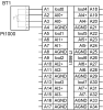
| Connection description | An example of module connection is shown in the following figure. |
| Module operation | |
| Module configuration | The module is operated, set up and diagnosed from the Mosaic development environment. |
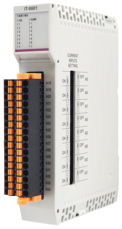
| Module configuration | On the right side of the module, there are accessible terminals on which jumpers are used to set individual channels for measuring current or voltage ranges. |
| Commissioning | On the module, the DIP switch in the left part of the case sets a unique address within one frame. The module is fully ready for operation after inserting it into the frame and turning on the power supply. |
| Module diagnostics | The basic diagnostic system of the module is part of its standard software. It has been in operation since the module power was turned on and works independently of the user. Diagnosed error states of the module and connected peripheral modules of the assembly are signaled in the status word of the module and on the module panel |
| Maintenance | |
| Description | The module does not require any maintenance under general installation conditions. |
| Notice | Because the module contains semiconductor components, it is necessary to follow the principles for working with electrostatic sensitive components when handling the removed cover. It is not allowed to directly touch the printed circuit boards without protective measures !!! |
| Warranty | |
| Generally | Warranty and complaint conditions are governed by the Terms and Conditions of Teco a.s. |
| Notice | You must meet all the conditions of this documentation before turning on the system. The system must not be put into service unless it has been verified and confirmed that the machinery meets the requirements of Directive 2006/42 / EC for machinery, in so far as it applies to them. |
Files for designers
TC800 - library of elements in DXF and DWG formats, v. 2025/01
493.14 kB
TC800 - element library for SchemataCAD, v. 2025/01
130.34 kB
EC - Declaration of Conformity
TC800 - CE declaration of conformity (cs)
292.20 kB
TC800 - CE Declaration of Conformity (en)
709.29 kB
- Examples of power connections for TC800 modules - ...ering the relay coils of the OR-8450 module and providing power for galvanically isolated sources for the analog part of the IT-8601 and OT-8651 modules. The required power of the source must be calculated according to the consumption from the VIO le...
- TC800 power supply sizing calculation and heat loss - ...nbsp; IT-8601 TXN 186 01 2 0,3 W 0,8 W 1,4 W 1,4 W IT-...
No data available.