
C-OR-0011M-800TXN 133 67
C-OR-0011M-800; CIB, 11x RO, NO contact, 230V / 16A (inrush current 800A)
| DI | |
|---|---|
| DI/AI | |
| DO | 11x RO |
| AI | |
| AO | |
| COM | 1x CIB slave |
| SENSOR |
| Picture | Variant | Variant description |
|---|---|---|

|
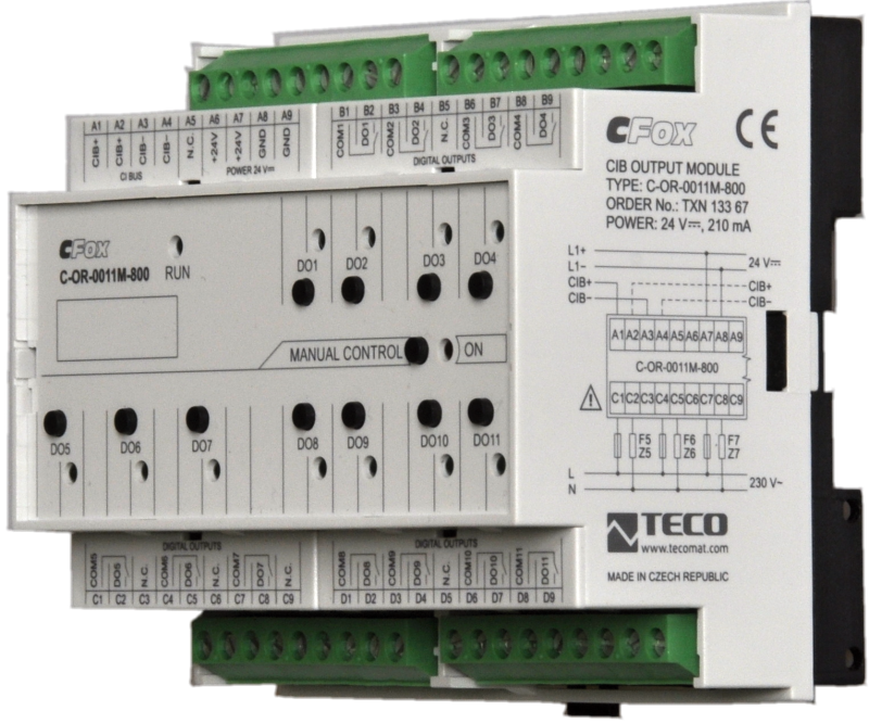
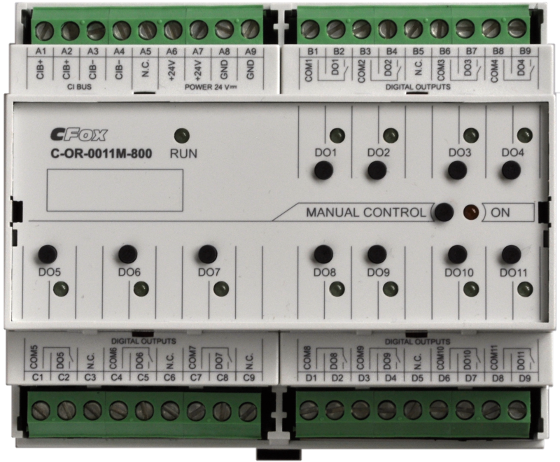
C-OR-0011M-800 |
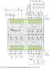
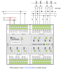
C-OR-0011M-800; CIB, 11x RO, switching contact, 230V / 16A (inrush current 800A)
Module on the CIB bus, which contains 11 relay outputs with a switching contact, each separately connected to the terminal board.
Module on the CIB bus, which contains 11 relay outputs with a switching contact, each separately connected to the terminal board.
| Order num. | TXN 133 67 |
|---|---|
| Teco code | TXN 133 67 |
| Categories | CFox - Modules on DIN rail |
| Tags | - |
| COM - System buses | |
|---|---|
| CIB - Common Installation Bus (R): Installation I/O bus | 1x CIB slave |
| RO - Parameters of binary relay outputs (group A) | |
| Number of relay outputs | 11 |
| Number of output groups | 3 |
| Output type | electromechanical relay, unprotected output |
| Contact type | NO - Normally Open |
| Diagnose | Alarm signaling on panel module |
| Switching current | 16 A max., 100 mA min. |
| Switching voltage | 250 V AC max., 5 V AC min., 30V DC max. |
| Short-term output overload - inrush | max. 800 A (max. 200 μs) |
| Contact closing time | typ. 10 ms |
| Contact opening time | typ. 5ms |
| Limit values of switched resistive load | max. 16A at 30 V DC or 230 V AC |
| Mechanical life | min. 5,000,000 cycles |
| Short-circuit protection | No |
| Treatment of inductive load | External RC element, varistor (AC), diode (DC) |
| Insulation voltage between outputs and internal circuits | 3750 V AC |
| Isolation voltage between groups of outputs to each other | 3750 V AC |
| Power supply | |
| Nominal supply voltage (V) | 24 V DC |
| Supply voltage, tolerances | 24 V DC ± 15% external power supply |
| Maximum power input | 4,5 W |
| Module thermal/power loss | 5 W |
| Maximum current consumption (mA) | 200 mA |
| Size and weight | |
| Weight approx. | 400 g |
| Product dimensions (width x height x depth) | 105 x 92 x 58 mm |
| Module width in multiples of M (17.5 mm) | 6M |
| Module width | 105 mm |
| Module height | 90 mm |
| Module depth | 58 mm |
| Operating conditions, product standards | |
| Product standard | ČSN EN 60730-1 ed. 2:2001 (mod IEC 60730-1:1999) |
| Protection class of electrical object | II, according to ČSN EN 61140 ed.3: 2016 (idt IEC 61140:2016) |
| IP rating (Ingress Protection) according to ČSN EN 60529: 1993 (idt IEC 529: 1989) | IP20 |
| Operating areas | Normal according to ČSN 33 2000-1: 2003 (IEC 364-1: 1992 mod) |
| Degree of pollution | 1, according to ČSN EN 60664-1 ed.2:2008 ( idt IEC 60664-1:2007) |
| Overvoltage category installation | II, according to EN 60664-1 ed_2: 2008 (idt IEC 60641-1: 2007) |
| Type of device | Module on DIN rail |
| Working position | Vertical |
| Type of operation (operating frequency) | Continuous |
| Ambient operating temperatures | -10 °C to + 55 °C |
| Operating temperature maximum (° C) | +55°C |
| Operating temperature minimum (° C) | -10°C |
| Operating relative humidity | from 10 % up to 95 % without condensation |
| Operating atmospheric pressure | min. 70 kPa (<3,000 m above sea level) |
| Storage temperatures | –25 °C to +70 °C |
| Electromagnetic compatibility, Mechanical endurance | |
| Electromagnetic compatibility / Emission | A, according to EN 55022: 1999 (mod CISPR22: 1997) |
| Emmisions - note | In premises where the use of radio and television receivers can be expected to be used a distance of 10 m from these devices may cause radio interference. In such a case, the user may be required to take appropriate action. |
| Electromagnetic compatibility / Immunity | min. according to ČSN EN 60730-1 ed.2: 2001 |
| Sinusoidal vibration endurance | 10 Hz to 57 Hz, amplitude 0,075 mm, 57 Hz to 150 Hz, acceleration 1 G (Fc test according to EN 60068-2-6: 1997 (idt IEC 68-2-6: 1995), 10 cycles per axis.) |
| Packaginng, transportation, storage | |
| Description | The module is packed in a paper box. This documentation is also part of the package. The outer packaging is carried out according to the scope of the order and the method of transport in a transport package provided with labels and other data necessary for transport. The product must not be exposed to direct weather conditions during transport and storage. Malting of the product is only allowed in clean rooms without conductive dust, aggressive gases and vapors. The most suitable storage temperature is 20 ° C |
| Installation | |
| Assembly description | The module is mounted in a vertical position on the U-rail ČSN EN 50022. Installation of the assembly (basic module and possibly peripheral modules) is performed according to TXV 004 13. |
| Attention! | The device may contain parts with dangerous voltages, covers being removed, or cabling manipulated, or disconnect the appropriate circuits or turn off the power !. |
| Connection | |
| Connection of power and system communication | terminal block with screw terminal 2.5 mm2 |
| Connection of inputs / outputs | terminal block with screw terminal 1.5 mm2 |
| Module operation | |
| Commissioning | The module is operated, set and diagnosed from the MOSAIC programming environment or other parameterization software. The module is ready for operation after connecting the supply voltage and the CIB bus. The HW address is indicated on the label on the module. |
| Module diagnostics | The basic diagnostics is performed internally and the result is available in the relevant registers of the Mosaic environment. |
| Maintenance | |
| Description | The module does not require any maintenance under general installation conditions. |
| Notice | Because the module contains semiconductor components, it is necessary to follow the principles for working with electrostatic sensitive components when handling the removed cover. It is not allowed to directly touch the printed circuit boards without protective measures !!! |
| Warranty | |
| Generally | Warranty and complaint conditions are governed by the Terms and Conditions of Teco a.s. |
| Notice | You must meet all the conditions of this documentation before turning on the system. The system must not be put into service unless it has been verified and confirmed that the machinery meets the requirements of Directive 89/392 / EEC, in so far as it applies to it. Documentation subject to change. |
HW documentation
C-OR-0011M-800 - Basic documentation
1.17 MB, (EN)
User manuals
Peripheral module on CIB-Common Installation Bus(R) (cs), TXV00413_01
14.01 MB
Peripheral modules on the CIB Common Installation Bus(R) (en), TXV00413_02
13.94 MB, (EN, RU, DE, UA)
Files for designers
Foxtrot 2 - library of elements in DXF and DWG formats, v. 2025/08.
21.80 MB
Foxtrot 2 - element library for SchemataCAD, v. 2025/08.
6.96 MB
EC - Declaration of Conformity
Foxtrot - EC Declaration of conformity
295.20 kB, (EN, RU, DE, UA)
- C-OR-0011M-800, relay outputs - The C-OR-0011M-800 module is equipped with 11 relays, separately terminated, with a switching contact. Continuous current in each output is 16 A, brief switching current up to 800 A (max. for 200 μ s) – see detailed information on th...
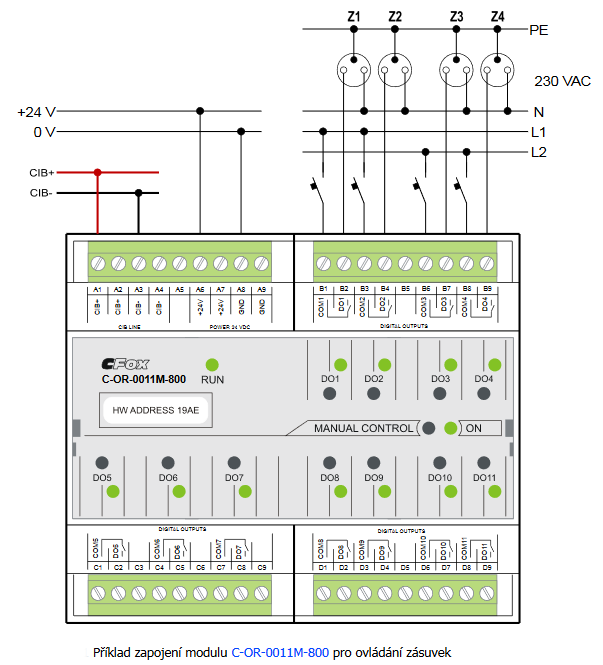
- Socket circuit control, module C-OR-0011M-800 - The most common is the control of socket circuits by relay outputs directly from the switchboard. The C-OR-0011M-800 module, for example, is suitable for standard socket circuits protected by a 16 A circuit breaker. The module is equipped wit...
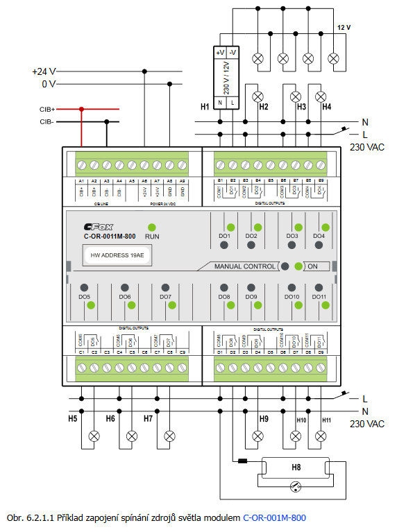
- Switching light sources 230 VAC, module C-OR-0011M-800 - The most universal module for switching light circuits is C-OR-0011M-800 . This module is equipped with 11 relay outputs with a 16 A switching contact , which is equipped with a tungsten pre-contact with a maximum switching current of 800 A for 20...
- Power dissipation of modules for calculation of switchboard heating - ...C-IR-0303M; CIB, 3x AI/DI, 2x RO-5A, 1x RO-16A C-IR-0303M 1,5 W TXN 133 67 C-OR-0011M-800; CIB, 11x RO, switching contact, 230V/16A (inrush 800A) C-OR-0011M-800 5,0 W...
- CIB power supply – principles, optimization - ...from CIB. However, there are modules, e.g. the C-HM-1121M , which are powered from 230VAC, or the C-OR-0008M , C-OR-0011M-800 , C-JC-0006M and C-IB-1800M , which can be optionally powered from a 24 or 27 VDC external power...
- 16 A relay (160 A switching current), the CFox and RFox peripheral modules - These relays are fitted in e.g. the C-OR-0011M-800 , C-LC-0202B , C-HM-1121M , R-HM-1121M peripheral modules, and others (see the information on the individual modules ). Tab. 1. The parameters of the actual relay cont...
- Control of socket circuits and sockets - ...ent of the switching element, we can use it: relay outputs located in the switchboard (typically C-OR-0008M , C-OR-0011M-800 modules, 16 A outputs of the C-HM-1121M module and their RFox variants), see this article...
- Switching of LED lighting, light bulbs, fluorescent lamps, etc. - ...with common contact, but only with relay outputs that are explicitly recommended for these loads - ie modules: C-OR-0011M-800 11 relay outputs with short-term switching current up to 800 A C-LC-0202B 2 relay outputs with short-ter...
- Switching power supply to the DSI, DALI, etc. ballasts - ...with a higher switching current: we recommend using modules fitted with relays with switching current of 800 A - e.g. the C-OR-0011M. If there are more than 4 simultaneously switching ballasts, it is necessary to thoroughly examine the maxi...
- Switching the lighting – 230 VAC incandescent bulbs , 12 VDC incandescent bulbs - The diagram shows the wiring of the C-OR-0008M module, which switches various types of loads - from incandescent bulbs, fluorescent tubes to the 12 V source for halogen lamps. The C-OR-0011-800 module can be used in a similar manner - its...
No data available.