

C-OR-0008MTXN 133 03
C-OR-0008M; CIB, 8x RO, changeover contact, 230V / 16A
| DI | |
|---|---|
| DI/AI | |
| DO | 8x RO NO/NC 16A/10A |
| AI | |
| AO | |
| COM | 1x CIB slave |
| SENSOR |
| Picture | Variant | Variant description |
|---|---|---|

|
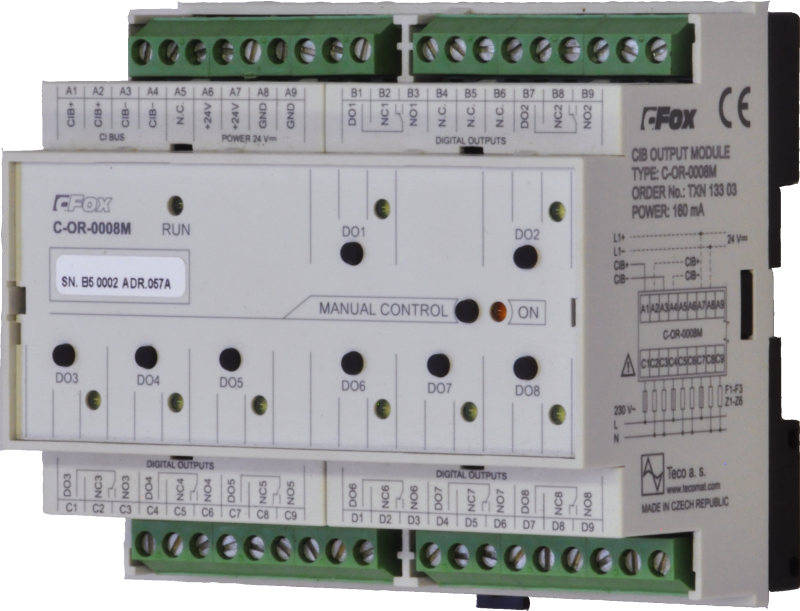
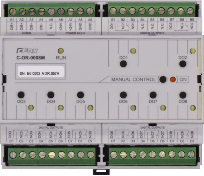
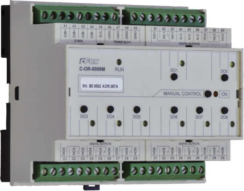
C-OR-0008M |
Module with a total of 8 relay outputs.
- It is connected to the basic module via a two-wire CIB Common installation BUS.
- Power supply either from the CIB bus (higher consumption limits the maximum number of modules on one CIB branch) or with amplification directly from a 24 V DC source.
- Each output has a make (16 A permanent) and break contact (10 A permanent).
- Each output has a separate LED indication on the front panel.
- The module can be switched to manual (service) mode and each output can be controlled separately with the buttons on the front panel.
- Switching and opening by contact in general.
- The relay outputs have increased resistance to inrush current of switching power supplies up to 80A.
- Suitable for switching LED bulbs, ballasts and capacitive transformers
| Order num. | TXN 133 03 |
|---|---|
| Teco code | TXN 133 03 |
| Categories | CFox - Modules on DIN rail |
| Tags | - |
| RO - Parameters of binary relay outputs (group A) | |
|---|---|
| Number of relay outputs | 8 |
| Number of output groups | 3 |
| Number of outputs in group | 1 |
| Organization of relay outputs into groups | Independently |
| Output type | electromechanical relay, unprotected output |
| Contact type | NO / NC changeover contact |
| Diagnose | Alarm signaling on panel module |
| Switching current | 16 A max. NO/10 A max NC, 100 mA min. |
| Switching voltage | 300 V max., 5 V min. |
| Short-term output overload - inrush | 80 A max. (20 ms max.) |
| Contact closing time | typ. 15 ms |
| Contact opening time | typ. 5ms |
| Mechanical life | min. 5,000,000 cycles |
| Short-circuit protection | No |
| Treatment of inductive load | External RC element, varistor (AC), diode (DC) |
| Insulation voltage between outputs and internal circuits | 3750 V AC |
| Notice! | An insulation voltage of 3750V AC is not guaranteed between the contacts on the common terminal block |
| Power supply | |
| Power supply from CIB - voltage | 24/27 V DC |
| Auxiliary power supply - voltage | 24 V DC, +- 10% |
| Typical power input | 4 W |
| Maximum power input | 4,5 W |
| Module thermal/power loss | 4 W |
| Maximum current consumption (mA) | 200 mA |
| Power supply from CIB - maximum current consumption (mA) | 160 mA |
| Galvanic separation of power supply from internal circuits | No |
| Size and weight | |
| Weight approx. | 350 g |
| Product dimensions (width x height x depth) | 105 x 92 x 58 mm |
| Module width in multiples of M (17.5 mm) | 6M |
| Module width | 105 mm |
| Module height | 92 mm |
| Module depth | 58 mm |
| Operating conditions, product standards | |
| Product standard | ČSN EN 61131-2 ed.2: 2008 (IEC 61131-2: 2007) и ČSN EN 60730-1 ed.4: 2017 (EN 60730-1: 2016) |
| Protection class of electrical object | I, according to ČSN EN 61140 ed.3: 2016 (idt IEC 61140:2016) |
| IP rating (Ingress Protection) according to ČSN EN 60529: 1993 (idt IEC 529: 1989) | IP20 |
| Operating areas | Normal, acc. ČSN 33 2000-1 ed.2: 2009 (mod IEC 60354-1:2005) |
| Degree of pollution | 1, according to ČSN EN 60664-1 ed.2:2008 ( idt IEC 60664-1:2007) |
| Overvoltage category installation | II, according to EN 60664-1 ed_2: 2008 (idt IEC 60641-1: 2007) |
| Type of device | Module on DIN rail |
| Working position | Vertical |
| Type of operation (operating frequency) | Continuous |
| Ambient operating temperatures | -10 °C to + 55 °C |
| Operating temperature maximum (° C) | +55°C |
| Operating temperature minimum (° C) | -10°C |
| Operating relative humidity | from 10 % up to 95 % without condensation |
| Operating atmospheric pressure | min. 70 kPa (<3,000 m above sea level) |
| Storage temperatures | –25 °C to +70 °C |
| Electromagnetic compatibility, Mechanical endurance | |
| Electromagnetic compatibility / Emission | B, according to EN 55022: 1999 (mod CISPR22: 1997) |
| Emmisions - note | In premises where the use of radio and television receivers can be expected to be used a distance of 10 m from these devices may cause radio interference. In such a case, the user may be required to take appropriate action. |
| Electromagnetic compatibility / Immunity | min. according to ČSN EN 60730-1 ed.2: 2001 |
| Sinusoidal vibration endurance | 10 Hz to 57 Hz, amplitude 0,075 mm, 57 Hz to 150 Hz, acceleration 1 G (Fc test according to EN 60068-2-6: 1997 (idt IEC 68-2-6: 1995), 10 cycles per axis.) |
| Packaginng, transportation, storage | |
| Description | The module is packed in a paper box. This documentation is also part of the package. The outer packaging is carried out according to the scope of the order and the method of transport in a transport package provided with labels and other data necessary for transport. The product must not be exposed to direct weather conditions during transport and storage. Malting of the product is only allowed in clean rooms without conductive dust, aggressive gases and vapors. The most suitable storage temperature is 20 ° C |
| Installation | |
| Attention! | The device may contain parts with dangerous voltages, covers being removed, or cabling manipulated, or disconnect the appropriate circuits or turn off the power !. |
| Connection | |
| Connection of power and system communication | connector with 2.5 mm2 screw terminal |
| Connection of inputs / outputs | connector with screw terminal 2.5 mm2 |
| Module operation | |
| Module configuration | LEDs on the front of the module are used to diagnose the condition. To set the button on the module as described in the diagrams section |
| Maintenance | |
| Description | The module does not require any maintenance under general installation conditions. |
| Notice | Because the module contains semiconductor components, it is necessary to follow the principles for working with electrostatic sensitive components when handling the removed cover. It is not allowed to directly touch the printed circuit boards without protective measures !!! |
| Warranty | |
| Generally | Warranty and complaint conditions are governed by the Terms and Conditions of Teco a.s. |
| Notice | You must meet all the conditions of this documentation before turning on the system. The system must not be put into service unless it has been verified and confirmed that the machinery meets the requirements of Directive 89/392 / EEC, in so far as it applies to it. Documentation subject to change. |
HW documentation
C-OR-0008M - Basic documentation
1.10 MB, (EN)
User manuals
Peripheral module on CIB-Common Installation Bus(R) (cs), TXV00413_01
14.01 MB
Peripheral modules on the CIB Common Installation Bus(R) (en), TXV00413_02
13.94 MB, (EN, RU, DE, UA)
Files for designers
Foxtrot 2 - library of elements in DXF and DWG formats, v. 2025/08.
21.80 MB
Foxtrot 2 - element library for SchemataCAD, v. 2025/08.
6.96 MB
EC - Declaration of Conformity
Foxtrot - EC Declaration of conformity
295.20 kB, (EN, RU, DE, UA)
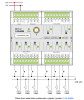
- Control of asynchronous motors for blinds and awnings, C-OR-0008M - ...(which usually causes damage to the motor drive). Fig. 1. An example of wiring the blinds motor control by the C-OR-0008M module Notes: Relay outputs with interlocking switching of both outputs; after switchin...
- C-OR-0008M, relay outputs - The C-OR-0008M module is equipped with 8 relays; each is separately terminated with a changeover contact. Continuous current on each output is 16A, inrush current up to 80 A (for max. 20 ms, it applies ONLY for the switching contact)- see the de...
- 16 A relay (80 A switching current), the CFox and RFox peripheral modules_kopie464 - These relays are fitted in e.g. the C-OR-0008M , C-OR-0202B , R-OR-0001B peripheral modules, and others (see the information on the individual modules ). The NO contact is designed as increased (inrush current 80 A), the NC con...
- Power dissipation of modules for calculation of switchboard heating - ...41 (single-channel external bus master CIB; 1,5M) CF-2141 4,0 W TXN 133 03 C-OR-0008M; CIB, 8x RO, switching contact, 230V/16A C-OR-0008M 4,0 W TXN 133 06...
- Ventilation and recuperation units - ...C-1203 Further it is possible to control electrical heating (16 A relay outputs, e.g. the C-OR-0008M ), to scan inputs from defective sensors (filter, etc.), from remote control (manual control e.g. from the bathroo...
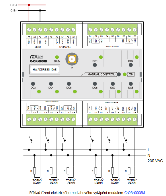
- Electric underfloor heating - ...directly to the flush box ( C-OR-0202B with a possibility of simultaneously measuring the floor temperature), or the C-OR-0008M module, which can switch up to 8 branches and can be placed in the distribution cabinet next to circuit breaker...
- CIB power supply – principles, optimization - ...odules are powered from CIB. However, there are modules, e.g. the C-HM-1121M , which are powered from 230VAC, or the C-OR-0008M , C-OR-0011M-800 , C-JC-0006M and C-IB-1800M , which can be optionally powered from a 24 or 27 V...
- 16 A relay (80 A switching current), the CFox and RFox peripheral modules - These relays are fitted in e.g. the C-OR-0008M , C-OR-0202B , R-OR-0001B peripheral modules, and others (see the information on the individual modules ). The NO contact is designed as increased (inrush current 80 A), the NC con...
- R-OR-0008M, relay outputs - The module is no longer for sale The R-OR-0008M module is functionally fully consistent with the C-OR-0008M module (identical inputs, outputs). The only difference is in communication. The module is in a wireless version – a periph...
- Control of socket circuits and sockets - ...ation requirement of the switching element, we can use it: relay outputs located in the switchboard (typically C-OR-0008M , C-OR-0011M-800 modules, 16 A outputs of the C-HM-1121M module and their RFox variants), see this articl...
- Switching power supply to the DSI, DALI, etc. ballasts - ...We recommend using a relay contact with minimum switching current of 80 A for switching a single ballast, such as the C-OR-0008M or C-LC-0202B (it can be stated that a relay with inrush switching current below 40 A is of very little u...
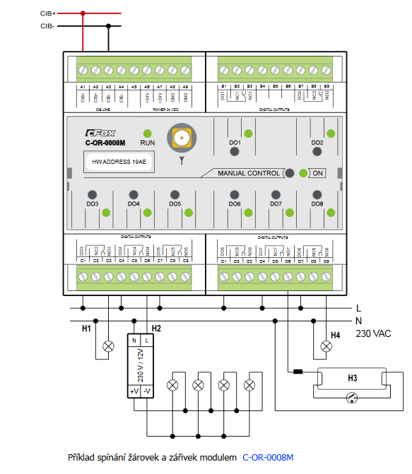
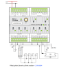
- Switching the lighting – 230 VAC incandescent bulbs , 12 VDC incandescent bulbs - The diagram shows the wiring of the C-OR-0008M module, which switches various types of loads - from incandescent bulbs, fluorescent tubes to the 12 V source for halogen lamps. The C-OR-0011-800 module can be used in a similar manner - its...
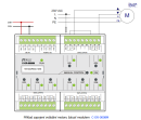
- Switching of external switching power supplies for LED power supplies (voltage and current). - ...ort time (so-called cold start according to the manufacturer's catalog sheet), therefore we recommend, for example, the C-OR-0008M module for their switching: Fig. 1 Example of switching switching power supplies for LED module C-OR-000...
- Switching of LED lighting, light bulbs, fluorescent lamps, etc. - ...th short-term switching current up to 800 A C-LC-0202B 2 relay outputs with short-term switching current up to 80 A C-OR-0008M 8 relay outputs with short-term switching current up to 80 A C-OR-0202B 2 relay outputs with short-term swit...
- The three-point controlled DANFOSS AMV 20 drive - An example of a three-point controlled regulation valve is shown in the following figures. The example uses a three-point controlled DANFOSS AMV 20, a drive with the 230 VAC supply voltage, power consumption 2 VA. The actuator is controlled b...
- Control of direct current motors for roller blinds - In order to control DC motors reversed by switching the polarity of supply voltage (motors for interior blinds, and such like), we recommend to use relay outputs with a switching contact, such as the C-OR-0202B . Fig. 1. An example o...
No data available.