

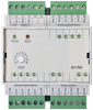
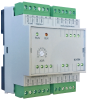
IC-1701TXN 117 01
IC-1701, 8x DI fast, 4x DO Fast
| DI | |
|---|---|
| DI/AI | |
| DO | |
| AI | |
| AO | |
| COM | |
| SENSOR |
| Picture | Variant | Variant description |
|---|---|---|

|
IC-1701 |
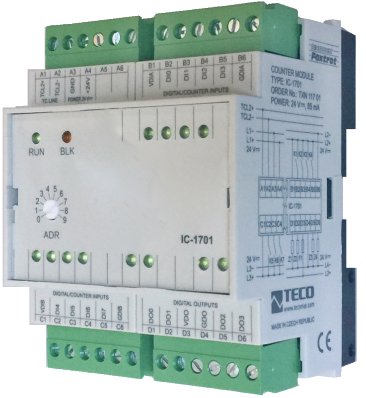
The IC-1701 expansion module contains 8 fast binary inputs with adjustable decision level and 4 fast transistor outputs usable as PWM outputs or for controlling up to 2 stepper motors. All inputs and outputs as well as individual groups are galvanically separated from the input voltage and TCL2 communication, and the status of each input is signaled on the module panel. The module is equipped with removable screw connectors.
| Order num. | TXN 117 01 |
|---|---|
| Teco code | TXN 117 01 |
| Categories | Foxtrot - I / O Expansion Modules (TCL2) |
| Tags | - |
| COM - System buses | |
|---|---|
| TCL2 - system I/O bus | 1x TCL2 slave |
| DI - Organization of binary inputs | |
| Total number of binary inputs | 8 |
| Number of groups of binary inputs | 2 |
| DI - Parameters of binary inputs DC (group A) | |
| Number of inputs in group | 4 |
| Common wire | minus |
| Combined input type | DI / HSC High Speed Counter |
| Galvanic isolation of inputs from internal/peripheral circuits | Yes, even between groups |
| Diagnostics | indication of energized input by LED on module panel |
| Input voltage for log. 0 | 0,25*VDI max. |
| Input voltage for log. 1 | min 0,6*VDI, typ VDI, max +30V DC |
| Input current at log. 1 (typ.) | 5 mA at 24 V DC |
| Delay from log. 0 to log. 1 | 2 μs |
| Delay from log. 1 to log. 0 | 2 μs |
| The minimum width of the captured pulse | 5 μs |
| Insulation voltage between inputs and internal circuits | 500 V |
| DO/RO - Organization of binary outputs | |
| Total number of binary outputs | 4 |
| Number of binary output groups | 1 |
| DO - Parameters of binary transistor outputs (group A) | |
| Parameters valid for the terminals | DO0-DO3 |
| Number of transistor outputs | 4 |
| Number of outputs in group | 4 |
| Output type | semiconductor output, half-bridge (push-pull) |
| Galvanic separation from internal circuits | Yes |
| Diagnostics | indication of energized output by LED on module panel |
| Switching voltage | 10 – 32 V DC |
| Switching current, output load | 2.7 A each output permanently, pulse 4 A |
| Output resistance | type. 0.3 Ω, max. 0.6 Ω |
| Switching time | typ. 1,6 μs |
| Opening time | typ. 0,6 μs |
| Residual current | max. 2 mA |
| Short circuit protection | Yes |
| Insulation voltage between outputs and internal circuits | 500 V |
| Insulation voltage between input and output groups | 500 V |
| Power supply | |
| Supply voltage, tolerances | 24 V DC ± 15% external power supply |
| Maximum power input | 2,5 W |
| Module thermal/power loss | 2,5 W |
| Internal protection | No |
| Size and weight | |
| Weight approx. | 150 g |
| Module width in multiples of M (17.5 mm) | 4M |
| Product dimensions (width x height x depth) | 70× 90 ×63 mm |
| Operating conditions, product standards | |
| Product standard | ČSN EN 61131-2:2008 (idt IEC 61131-2:2007) - Programmable control units |
| Protection class of electrical object | III, according to ČSN EN 61140 ed.3: 2016 (idt IEC 61140:2016) |
| IP rating (Ingress Protection) according to ČSN EN 60529: 1993 (idt IEC 529: 1989) | IP20 |
| Operating areas | Normal, acc. ČSN 33 2000-1 ed.2: 2009 (mod IEC 60354-1:2005) |
| Degree of pollution | 1, according to ČSN EN 60664-1 ed.2:2008 ( idt IEC 60664-1:2007) |
| Overvoltage category installation | II, according to EN 60664-1 ed_2: 2008 (idt IEC 60641-1: 2007) |
| Type of device | Module on DIN rail |
| Working position | Vertical |
| Type of operation (operating frequency) | Continuous |
| Ambient operating temperatures | -20 °C to + 55 °C |
| Operating relative humidity | from 10 % up to 95 % without condensation |
| Operating atmospheric pressure | min. 70 kPa (<3,000 m above sea level) |
| Storage temperatures | –25 °C to +70 °C |
| Electromagnetic compatibility, Mechanical endurance | |
| Electromagnetic compatibility / Emission | A, according to EN 55032 ed. 2: 2017 (idt CISPR 32: 2015) |
| Emmisions - note | In premises where the use of radio and television receivers can be expected to be used a distance of 10 m from these devices may cause radio interference. In such a case, the user may be required to take appropriate action. |
| Electromagnetic compatibility / Immunity | min. as required by EN 61131-2: 2007 |
| Sinusoidal vibration endurance | 10 Hz to 57 Hz, amplitude 0,075 mm, 57 Hz to 150 Hz, acceleration 1 G (Fc test according to EN 60068-2-6: 1997 (idt IEC 68-2-6: 1995), 10 cycles per axis.) |
| Packaginng, transportation, storage | |
| Description |
The module is packed in a paper box. This documentation is also part of the package. The outer packaging is carried out according to the scope of the order and the method of transport in a transport package provided with labels and other data necessary for transport. The product must not be exposed to direct weather conditions during transport and storage. Malting of the product is only allowed in clean rooms without conductive dust, aggressive gases and vapors. The most suitable storage temperature is 20 ° C |
| Installation | |
| Assembly description | The peripheral module is mounted in a vertical position on the U-rail ČSN EN 50022. Installation of the assembly (basic module and possibly peripheral modules) is performed according to TXV 004 12. |
| Connection | |
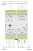
| Connection description |
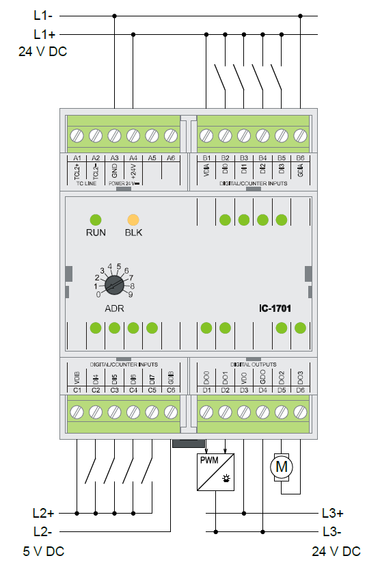
Wiring notes: 1. The VDIA, VDIB and VDO voltages can each be supplied from a different source or even from the same source together with a +24 V system supply. 2. Internally, the groups are galvanically separated from each other and from the internal circuits. |
| Connection of power and system communication | connector with 2.5 mm2 screw terminal |
| Connection of inputs / outputs | connector with screw terminal 2.5 mm2 |
| Module operation | |
| Module configuration | The module is operated, set up and diagnosed from the Mosaic development environment. |
| Commissioning | The module is ready for operation after connecting the supply voltage. The address within the system is set to the Napanel (in the range 0 to 9). Other parameters are set in the MOSAIC programming environment. The exact setting procedure is given in the TXV 004 10 documentation. Further work is performed in the MOSAIC development environment. |
| Module diagnostics | The basic diagnostic system of the module is part of its standard software. It has been in operation since the module power was turned on and works independently of the user. Diagnosed module error states are listed in TXV 004 10. |
| Maintenance | |
| Instructions | The module does not require any maintenance if the general conditions for installation are observed. The operations that require the assembly or disassembly of the module are always performed with the TCL2 bus switched off and the + 24V supply. |
| Warranty | |
| Generally | Warranty and complaint conditions are governed by the Terms and Conditions of Teco a.s. |
| Notice | You must meet all the conditions of this documentation before turning on the system. The system must not be put into service unless it has been verified and confirmed that the machinery meets the requirements of Directive 89/392 / EEC, in so far as it applies to it. Documentation subject to change. |
HW documentation
IC-1701 - Basic documentation
1.11 MB, (EN)
Files for designers
Foxtrot 2 - library of elements in DXF and DWG formats, v. 2025/08.
21.80 MB
Foxtrot 2 - element library for SchemataCAD, v. 2025/08.
6.96 MB
EC - Declaration of Conformity
Foxtrot - EC Declaration of conformity
295.20 kB, (EN, RU, DE, UA)
- IC-1701 - The IC-1701 expansion module contains 8 fast binary inputs with adjustable decision level and 4 fast transistor outputs usable as PWM outputs or for controlling up to 2 stepper motor drivers. All inputs and outputs as well as individual groups are g...
- Peripheral module address fixation on TCL2 - ...0100 - 01xx 2.4 a vyšší 1.4 * IC-1701 všechny verze 2.0 a vyšší ...
- Power dissipation of modules for calculation of switchboard heating - ...116 51 OT-1651, 4xAO: 0-10V/ 4-20mA, GO OT-1651 4,5 W TXN 117 01 IC-1701, 8x DI fast, 4x DO fast (fast switching) IC-1701 2,5 W TXN 117 51 G...
No data available.