

IB-1301TXN 113 01
IB-1301, 12xDI 24 VAC/DC, GO
| DI | 4x DI/HSC 8x DI |
|---|---|
| DI/AI | |
| DO | |
| AI | |
| AO | |
| COM | 1x TCL2 (slave) |
| SENSOR |
| Picture | Variant | Variant description |
|---|---|---|

|
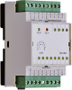
IB-1301 |
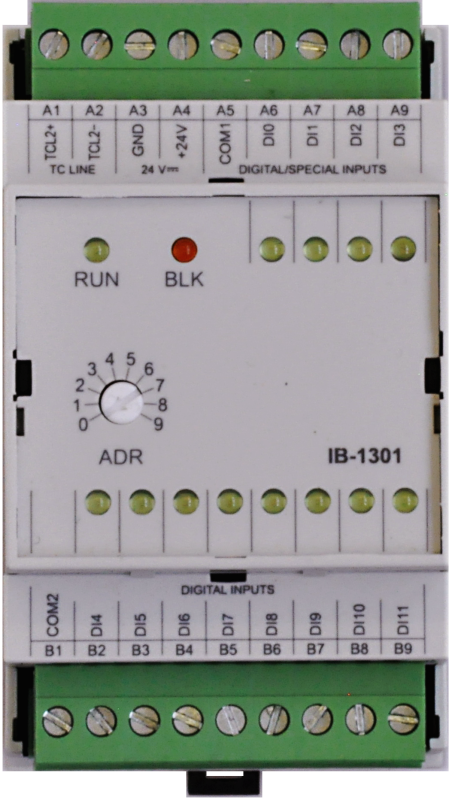
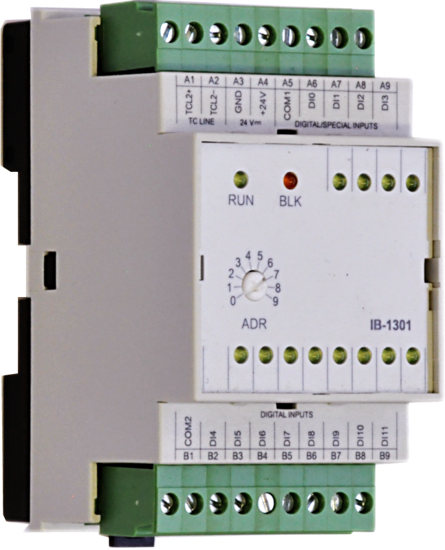
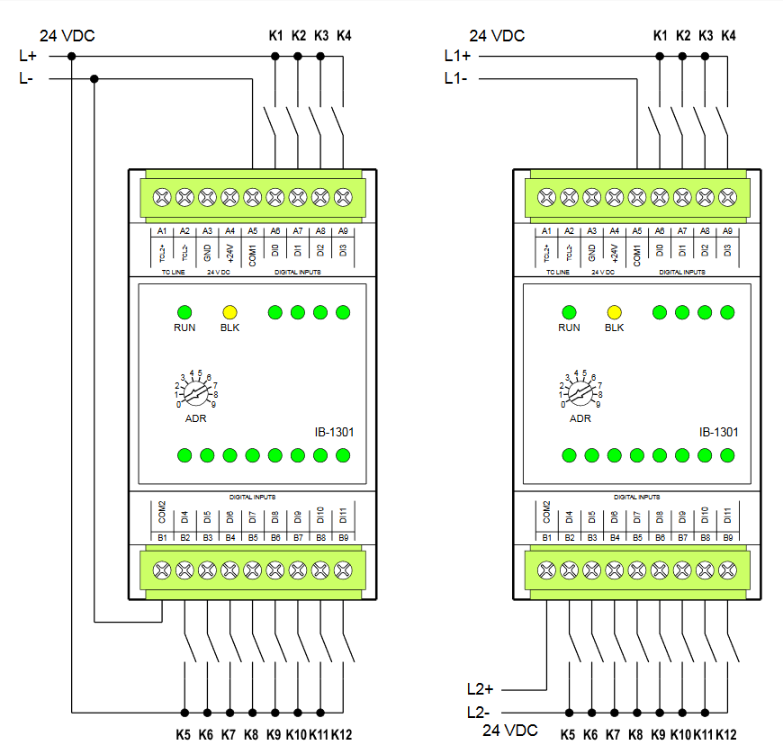
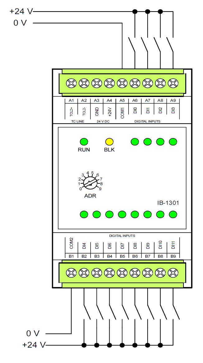
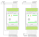
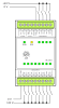
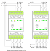
The IB-1301 expansion module is designed for the scanning of up to 12 binary signals 24 V DC with a common pole (minus or plus to way of connection), type 1 according to ČSN EN 61131. The module is equipped with removable screw-type connector. Inputs DI0 to DI3 allow to carry out a special functions conform to inputs on CP-1004 basic module. The inputs are galvanically isolated from the internal circuits (including power supply and communication) and groups of inputs are separated one from another. The status of each input is indicated by LED at the front module panel.
| Order num. | TXN 113 01 |
|---|---|
| Teco code | TXN 113 01 |
| Categories | Foxtrot - I / O Expansion Modules (TCL2) |
| Tags | - |
| COM - System buses | |
|---|---|
| TCL2 - system I/O bus | 1x TCL2 slave |
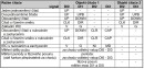
| DI - Organization of binary inputs | |
| Number of groups of binary inputs | 2 |
| Organization of binary inputs into groups |
4x DI/HSC (DI0-DI3) 8x DI (DI4-DI11) |
| DI - Parameters of binary inputs DC (group A) | |
| Parameters valid for inputs on the terminals | DI0-DI3 |
| Number of inputs in group | 4 |
| Common wire | minus/plus |
| Input type | Type 1 (IEC) |
| Galvanic isolation of inputs from internal/peripheral circuits | Yes |
| Diagnostics | indication of energized input by LED on module panel |
| Input voltage for log. 0 | 0 V DC; -5 V DC min.; +5 V DC max. |
| Input voltage for log. 1 | 24 V DC; 15 V DC min.; 30 V DC max. |
| Input current at log. 1 (typ.) | 10 mA typ. |
| Delay from log. 0 to log. 1 | 5 μs |
| Delay from log. 1 to log. 0 | 5 μs |
| The minimum width of the captured pulse | 50 μs |
| DI - Parameters of DC binary inputs (group B) | |
| Number of inputs in group | 8 |
| Common wire | minus/plus |
| Input type (IEC) | Type 1 (IEC) - passive |
| Galvanic separation of inputs from internal circuits | Yes |
| Diagnostics | indication of energized input by LED on module panel |
| Pulse input overload capacity | max. 30 V (t < 10 ms) |
| Input voltage for log. 0 | 0 V DC; -5 V DC min.; +5 V DC max. |
| Input voltage for log. 1 | +24 V DC; min. +15 V DC; max. +30 V DC |
| Input current at log. 1 (typ.) | typ. 5 mA |
| Delay from log. 0 to log. 1 | 5 ms |
| Delay from log. 1 to log. 0 | 5 ms |
| The minimum width of the captured pulse | 50 μs |
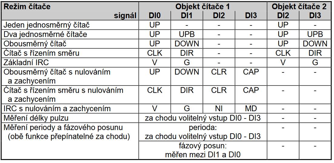
| HSC - Special functions of binary inputs / counters | |
| Unidirectional counter (UP) | 2x (DI0); (DI2) |
| Two unidirectional counters (UP / UPB) | 2x (DI0/DI2); (DI2/DI3) |
| Bidirectional counter (UP/DOWN) | 2x (DI0/DI1); (DI2/DI3) |
| Counter with direction control (CLK/DIR) | 2x (DI0/DI1); (DI2/DI3) |
| Bi-directional counter with reset and intercept (UP / DOWN / CLR / CAP) | 1x (DI0/DI1/DI2/DI3) |
| Counter with direction control with reset and latch (CLK / DIR / CLR / CAP) | 1x (DI0/DI1/DI2/DI3) |
| IRC Basic (V/G) | 2x (DI0/DI1); (DI2/DI3) |
| IRC with Zero and Capture (V / G / NI / MD) | 1x (DI0/DI1/DI2/DI3) |
| Measure the pulse length | 4x (DI0,DI1, DI2, DI3) |
| Period measurement | 4x (DI0,DI1, DI2, DI3) |
| Used shortcuts |
UP - pulse input for counter increment UPB - pulse input for counter increment B DOWN - pulse input for counter decrement CLK - pulse input for counter DIR - counter direction CLR - counter reset CAP - capture counter value V - first IRC track G - second IRC track NI - zero pulse IRC MD - measuring touch |
| HSC - Counter input parameters | |
| Counter: Input frequency / resolution | 5 kHz/1 pulse |
| Pulse width | min. 50 μs |
| Delay from log. 0 per log. 1 | 5 μs |
| Delay from log. 1 per log. 0 | 5 μs |
| Range of registers | up to 32 bits, 0 to 4 294 967 296 |
| HSC - Parameters of incremental encoder input (IRC) | |
| Frequency of symmetrical signal (V, G) | 1,25 kHz |
| Pulse Width (V, G, NI, MD) | min. 50 μs |
| Delay from log. 0 per log. 1 | 5 μs |
| Delay from log. 1 per log. 0 | 5 μs |
| Range of registers | up to 32 bits, 0 to 4 294 967 296 |
| HSC - Pulse length, period and phase shift measuring input parameters | |
| Input frequency | 0.1 to 5000 Hz |
| Pulse width | 50 μs to 10 s |
| Absolute measurement error | max. ±10 μs |
| Power supply | |
| Supply voltage, tolerances | 24 V DC, +25%, -15%, SELV |
| Typical power input | 1 W |
| Maximum power input | 2,5 W |
| Module thermal/power loss | 3 W |
| Maximum current consumption (mA) | 100 mA |
| Galvanic separation of power supply from internal circuits | No |
| Internal protection | Yes, PTC reversible fuse |
| Size and weight | |
| Weight approx. | 105 g |
| Module width in multiples of M (17.5 mm) | 3M |
| Product dimensions (width x height x depth) | 52 x 90 x 58 mm |
| Operating conditions, product standards | |
| Product standard | ČSN EN 61131-2:2008 (idt IEC 61131-2:2007) - Programmable control units |
| Protection class of electrical object | III, according to ČSN EN 61140 ed.3: 2016 (idt IEC 61140:2016) |
| IP rating (Ingress Protection) according to ČSN EN 60529: 1993 (idt IEC 529: 1989) | IP20 |
| Operating areas | Normal, acc. ČSN 33 2000-1 ed.2: 2009 (mod IEC 60354-1:2005) |
| Degree of pollution | 1, according to ČSN EN 60664-1 ed.2:2008 ( idt IEC 60664-1:2007) |
| Overvoltage category installation | II, acc. ČSN EN 60664-1:2004 (mod IEC 606641:1992) |
| Type of device | Module on DIN rail |
| Type of operation (operating frequency) | Continuous |
| Ambient operating temperatures | -20 °C to + 55 °C |
| Operating relative humidity | from 10 % up to 95 % without condensation |
| Operating atmospheric pressure | min. 70 kPa (<3,000 m above sea level) |
| Storage temperatures | –25 °C to +70 °C |
| Electromagnetic compatibility, Mechanical endurance | |
| Electromagnetic compatibility / Emission | A, according to EN 55022: 1999 (mod CISPR22: 1997) |
| Emmisions - note | In premises where the use of radio and television receivers can be expected to be used a distance of 10 m from these devices may cause radio interference. In such a case, the user may be required to take appropriate action. |
| Electromagnetic compatibility / Immunity | min. as required by EN 61131-2: 2007 |
| Sinusoidal vibration endurance | 10 Hz to 57 Hz, amplitude 0,075 mm, 57 Hz to 150 Hz, acceleration 1 G (Fc test according to EN 60068-2-6: 1997 (idt IEC 68-2-6: 1995), 10 cycles per axis.) |
| Packaginng, transportation, storage | |
| Description |
The module is packed in a paper box according to the internal packing instructions. The package also includes documentation. The outer packaging is carried out according to the scope of the order and the method of transport in a transport package provided with transport labels and other data necessary for transport. Transport from the manufacturer is carried out in the manner agreed upon when ordering. The transport of the product by the customer's own means must be carried out by covered means of transport, in the position specified by the label on the packaging. The box must be stored in such a way that it does not move spontaneously and the outer packaging is not damaged. The product must not be exposed to direct weather conditions during transport and storage. Transport is permitted at temperatures of -25 ° C to +70 ° C, relative humidity of 10% to 95% (non-condensing) and a minimum atmospheric pressure higher than 70 kPa. The product may only be stored in clean rooms free of conductive dust, aggressive gases and vapors. The most suitable storage temperature is 20 ° C. |
| Installation | |
| Assembly description | The basic module is mounted in a vertical position on the U-rail ČSN EN 50022. The installation of the assembly (basic module and possibly peripheral modules) is performed according to TXV00410. |
| Connection | |
| Connection of power and system communication | connector with 2.5 mm2 screw terminal |
| Connection of inputs / outputs | connector with screw terminal 2.5 mm2 |
| Module operation | |
| Module configuration | The module is operated, set up and diagnosed from the Mosaic development environment. |
| Commissioning | The module is ready for operation after connecting the supply voltage. The address within the system is set on the module panel (in the range 0 to 9). Other parameters are set in the Mosaic programming environment. The exact setting procedure is given in the TXV 004 12.01 documentation. Other activities are performed in the MOSAIC development environment. |
| Module diagnostics | The basic diagnostic system of the module is part of its standard software. It has been in operation since the module power was turned on and works independently of the user. Diagnosed module error states are listed in TXV 004 10.01 |
| Maintenance | |
| Description | The module does not require any maintenance under general installation conditions. The operations in which a part of the module has to be dismantled must always be carried out with the supply voltage disconnected. |
| Warranty | |
| Generally | Warranty and complaint conditions are governed by the Terms and Conditions of Teco a.s. |
| Warning |
All conditions of this documentation must be met before switching on the system, otherwise the protection provided by the device may be compromised. The system must not be put into service unless it has been verified and confirmed that the machinery of which the Foxtrot system is a part complies with the requirements of Directive 89/392 / EEC, in so far as it applies to them. All repairs and servicing of the product are performed exclusively by the manufacturer or a person authorized by him. The person performing the system installation is responsible for the safety of the system. |
HW documentation
IB-1301 - Basic documentation
1.17 MB, (EN)
Scheme
IB-1301
75.43 kB
IB-1301
87.90 kB
Files for designers
Foxtrot 2 - library of elements in DXF and DWG formats, v. 2025/08.
21.80 MB
Foxtrot 2 - element library for SchemataCAD, v. 2025/08.
6.96 MB
EC - Declaration of Conformity
Foxtrot - EC Declaration of conformity
295.20 kB, (EN, RU, DE, UA)
- IB-1301, a module of 24V binary inputs - The expansion module IB-1301 is designed to scan up to twelve 24 VDC binary signals with a common terminal (plus or minus, according to the wiring), type 1 (in accordance with EN 61131). The DI0 ÷ DI3 inputs allow the implemen...
- Peripheral module address fixation on TCL2 - ...102 všechny verze 1.6 a vyšší IB-1301 0600 a vyšší 0100 - 05xx 3.8 a vyšší...
- Power dissipation of modules for calculation of switchboard heating - ...UC-1205; GSM gate, dual band (900/1800MHz) UC-1205 3,0 W TXN 113 01 IB-1301, 12xDI 24 VAC/DC, GO IB-1301 3,0 W TXN 114 01 OS-1401, 12xDO 24 VDC...
- TCL2 bus – the principles of design and installation - The peripheral modules on the TCL2 bus (e.g. IB-1301) of one PLC Foxtrot configuration (i.e. all peripheral modules controlled by one basic module) must be interconnected via a bus connection, which is plugged in the terminals in the upper left edg...
- The FOXTROT peripheral modules - ...les, master modules and special modules) has a dedicated separate address space, so their addresses cannot overlap (e.g. the IB-1301 peripheral module, the CF-1141 external master module and the ID-14 panel can have a set identical address 0). &n...
- Measuring the amount of precipitation, the tipping bucket rain gauge - ...design, should be connected in the same way. It can be connected to any counter input of the system (i.e. the C-AM-0600 and IB-1301 inputs), or to standard digital inputs; however, in this case the minimum pulse width of the sensor must be verified,...
- Metering the consumption of 1ph network, the 9901M and ED11.M electricity meter, measuring t - ...e connected e.g. to the C-AM-0600I module; these meters can also be connected to standard binary 24 V inputs (e.g. the IB-1301 peripheral module), but some electricity meters have a limited range of voltage and current in the S0 output switched...
- extension modules ib, os - Why IB-1301 and OS -1401 modules often fail with an error 4301. How can they be protected?