

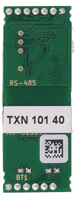

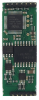
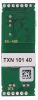


SE-0140, TCL2 Master - ExpanderTXN 101 40
SE-0140, Expander 1x Master system bus TCL2 for Foxtrot 2; own power supply, galvanic isolation, bus impedance termination
| DI | |
|---|---|
| DI/AI | |
| DO | |
| AI | |
| AO | |
| COM | 1x TCL2 Master |
| SENSOR |
| Picture | Variant | Variant description |
|---|---|---|

|
SE-0140, TCL2 Master - Expander |
SE-0140 Expander TCL2 system bus master for Foxtrot 2.
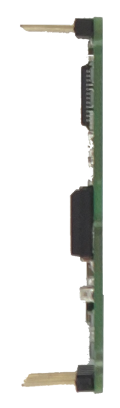
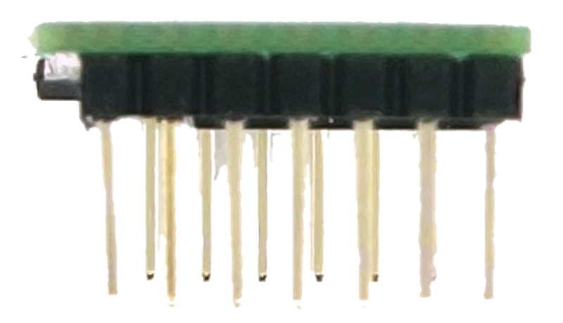
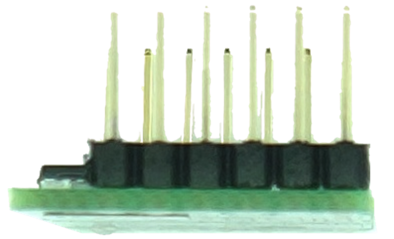
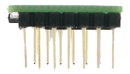
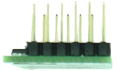
The submodule is inserted into the basic module in one or both free slots for serial channels.
The submodule is inserted into the basic module in one or both free slots for serial channels.
| Order num. | TXN 101 40 |
|---|---|
| Teco code | TXN 101 40 |
| Categories | Foxtrot 2 - Accessories for basic modules, TC800 - Positioning and counter modules |
| Tags | - |
| COM - System buses | |
|---|---|
| TCL2 - system I/O bus | 1x TCL2 master |
| TCL2 - Range of one branch of the system I/O bus | 10 I / O modules + 4 operator panels + 6 serial channels |
| The communication rate of the system I / O bus | 345 kbps |
| Signal output level | 3 V typ. |
| System I / O bus terminating resistor | 120 Ω |
| Receiver sensitivity | ±200 mV min. |
| Max. length of connected line | 400 m |
| Power supply | |
| Supply voltage, tolerances | The submodule is powered from the power supply the terminal device in which it is installed. |
| Size and weight | |
| Weight approx. | 7 g |
| Product dimensions (width x height x depth) | 15,5 × 42 × 3,5 mm |
| Operating conditions, product standards | |
| Product standard | ČSN EN 61131-2:2008 (idt IEC 61131-2:2007) - Programmable control units |
| Protection class of electrical object | III, according to ČSN EN 61140 ed.3: 2016 (idt IEC 61140:2016) |
| Operating areas | Normal, acc. ČSN 33 2000-1 ed.2: 2009 (mod IEC 60354-1:2005) |
| Degree of pollution | 1, according to ČSN EN 60664-1 ed.2:2008 ( idt IEC 60664-1:2007) |
| Overvoltage category installation | II, according to EN 60664-1 ed_2: 2008 (idt IEC 60641-1: 2007) |
| Type of device | Submodule |
| Type of operation (operating frequency) | Continuous |
| Ambient operating temperatures | -20 °C to + 55 °C |
| Operating relative humidity | from 10 % up to 95 % without condensation |
| Operating atmospheric pressure | min. 70 kPa (<3,000 m above sea level) |
| Storage temperatures | –25 °C to +70 °C |
| Connection | |
| Connection description | Terminal communication interfaces are typically equipped with connectors. The connection of the connectors is specified in the documentation of the respective system where the submodule is used. |
| Module operation | |
| Commissioning | The submodules contain solder jumpers that are used to connect a terminating resistor network. They are marked "BT1" for the first channel and "BT2" for the second channel. By default, submodules are delivered with interconnected jumpers. |
| Maintenance | |
| Notice | Because the module contains semiconductor components, it is necessary to follow the principles for working with electrostatic sensitive components when handling the removed cover. It is not allowed to directly touch the printed circuit boards without protective measures !!! |
| Warranty | |
| Generally | Warranty and complaint conditions are governed by the Terms and Conditions of Teco a.s. |
| Notice | You must meet all the conditions of this documentation before turning on the system. The system must not be put into service unless it has been verified and confirmed that the machinery meets the requirements of Directive 2006/42 / EC for machinery, in so far as it applies to them. |
HW documentation
SE-0140 - Basic documentation
77.73 kB
SE-0140 - Basic documentation
724.28 kB, (EN)
EC - Declaration of Conformity
Foxtrot 2 - EC Declaration of conformity (en)
590.59 kB, (EN, RU, DE, UA)
- TC800 CENTRAL MODULES - ...This bus uses metal cables to connect, corresponds to the RS-485 interface and must be terminated at both ends. Submodules SE-0140 contain the end of the bus and must always be at its end. At the other end, the bus must be connected to the last mod...
- TECOMAT TC800 SYSTEM FEATURES - ...on is to use older peripheral modules from the Foxtrot system to the TC800, this is made possible by the installation of the SE-0140 submodule (TXN 101 40) in the central TC800 module. This submodule mediates TCL2 bus emulation and thus the connectio...
- Analog Input Module Capacity for Foxtrot 2 PLC - ...puts, for 160 analog inputs you will need 2 fully occupied TCL2 buses. One on CP-2090 interface, second one on an additional SE-0140 sub-module inserted to CP-2090's slot. These modules have multiplexed inputs. The sample transfer time for one in...
- Two TCL2 Buses in a Single PLC - Yes, it is possible. It can be used SE-0140 submodule, it is an additional TCL2 interface. Each PLC Foxtrot CP-20xx is equipped with 2 slots for submodules, both of them can be fitted with SE-0140. By this you can realize 3 TCL2 lines on CPU, ie. th...