


MR-0105TXN 101 05
MR-0105, 1x RS-485, 2x RS-232 (FOXTROT only), GO with its own power supply and auto-identification
| DI | |
|---|---|
| DI/AI | |
| DO | |
| AI | |
| AO | |
| COM | |
| SENSOR |
| Picture | Variant | Variant description |
|---|---|---|

|
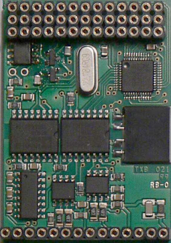
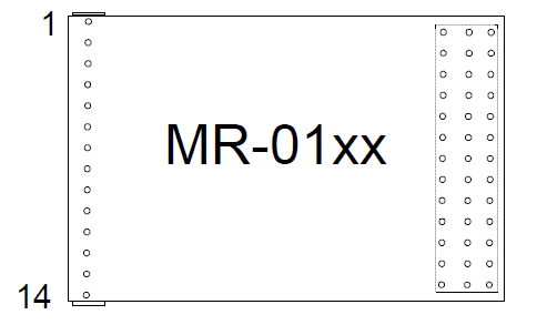
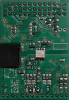
MR-0105 |
The MR-0105 communication submodule is designed for the first generation Foxtrot as an optional interface for channels CH2, CH3, CH4 on the central module. It contains 1x RS-485, 2x RS-232 interfaces including galvanic isolation from the system and power supply circuits of galvanic isolation.
| Order num. | TXN 101 05 |
|---|---|
| Teco code | TXN 101 05 |
| Categories | Foxtrot 1 - Accessories for basic modules |
| Tags | Sales and production discontinued |
| COM - Serial channels | |
|---|---|
| Number of internal RS-232 serial channels | 2 |
| Max. baud rate (RS-232) | 200 kBd |
| Receiver input resistance (RS-232) | min. 7 kOhm |
| Signal output level (RS-232) | typ. ±8 V |
| Max. length of connected line (RS-232) | 15 m |
| Number of internal RS-485 serial channels | 1 |
| Max. baud rate | 2 MBd |
| Receiver sensitivity (RS-485) | min. ±200 mV |
| Signal output level (RS-485) | typ. 3,7 V |
| Max. length of connected line (RS-485) | 1200 m |
| Note on cable length | The maximum length applies to twisted and shielded cable and communication speed max. 120 kBd. |
| Power supply | |
| Supply voltage, tolerances | The submodule is powered from the power supply the terminal device in which it is installed. |
| Maximum power input | < 1 W |
| Galvanic separation of power supply from internal circuits | No |
| Insulation voltage of galvanic separation | 1 000 VDC |
| Size and weight | |
| Weight approx. | 50 g |
| Product dimensions (width x height x depth) | 35,6 x 52 x 10 mm |
| Operating conditions, product standards | |
| Product standard | ČSN EN 61131-2:2008 (idt IEC 61131-2:2007) - Programmable control units |
| Protection class of electrical object | III, according to ČSN EN 61140 ed.3: 2016 (idt IEC 61140:2016) |
| Operating areas | Normal, acc. ČSN 33 2000-1 ed.2: 2009 (mod IEC 60354-1:2005) |
| Degree of pollution | 2, according to ČSN EN 60664-1 ed.2: 2008 (idt IEC 60664-1: 2007) |
| Overvoltage category installation | II, according to EN 60664-1 ed_2: 2008 (idt IEC 60641-1: 2007) |
| Type of operation (operating frequency) | Continuous |
| Ambient operating temperatures | -20 °C to + 55 °C |
| Operating temperature maximum (° C) | +55°C |
| Operating temperature minimum (° C) | 0°C |
| Operating relative humidity | from 10 % up to 95 % without condensation |
| Operating atmospheric pressure | min. 70 kPa (<3,000 m above sea level) |
| Storage temperatures | –25 °C to +70 °C |
| Packaginng, transportation, storage | |
| Description |
The submodule is packed in a paper box according to the internal packing instructions. This documentation is also part of the package. The outer packaging is carried out according to the scope of the order and the method of transport in transport packaging provided with transport labels and other data necessary for transport. Transport from the manufacturer is carried out in the manner agreed upon when ordering. The transport of the product by the customer's own means must be carried out by covered means of transport, in the position specified by the label on the packaging. The box must be stored in such a way that it does not move spontaneously and the outer packaging is not damaged. The product must not be exposed to direct weather conditions during transport and storage. Transport is permitted at temperatures of -25 ° C to 70 ° C, relative humidity of 10% to 95% (non-condensing) and a minimum atmospheric pressure higher than 70 kPa. The product may only be stored in clean rooms free of conductive dust, aggressive gases and vapors. The most suitable storage temperature is 20 ° C. |
| Installation | |
| Attention! | The modules contain components sensitive to electrostatic charge, so we observe them principles for working with these circuits! We handle only on the module disconnected from the power supply! When replacing the submodules, the correctness of the deployment must be carefully checked of the submodule cavities against the tips on the motherboard. The tubes have no coding position and incorrect installation, may occur when the power is turned on again damage to the submodule or even the motherboard !!! |
| Exchangeable submodules |
The installation of the submodule in the terminal device is always described in the documentation of the respective device. The submodule is mounted on the tips in the terminal device so that the 14-socket socket of the submodule is exactly opposite the 14-pin connector and the 13-socket socket is mounted on the tips of the connector, three-row connector. |
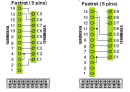
| Connection | |
| Description |
Terminal communication interfaces are typically equipped with connectors. Connection connectors is specified in the documentation of the respective system where the submodule is used. |
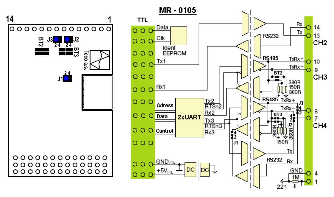
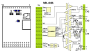
| Module operation | |
| Module configuration | The MR-0106 submodule has solder jumpers on the printed circuit board in the position marked 4. The CH4 channel works as an RS-485 interface. Jumpers BT2 and BT3 connect the impedance termination for the RS-485 line when the device is at the end of the communication line. By default, submodules are supplied with the most commonly used RS-485 settings, without termination. The block diagrams in the following figures illustrate the meaning, location and connection of the individual jumpers. |
| Warranty | |
| Generally | Warranty and complaint conditions are governed by the Terms and Conditions of Teco a.s. |
| Warning | You must meet all the conditions of this documentation before turning on the system. The system must not be put into service unless it has been verified and confirmed that the machinery of which the control system forms part complies with the requirements of Directive 89/392 / EEC, in so far as it applies to them. |
HW documentation
MR-0105/106/115 Basic documentation
179.35 kB
User manuals
OVERVIEW OF TECOMAT SUB-MODULES (en)
671.90 kB, (EN)
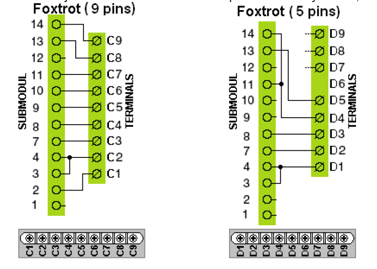
- MR-0105, MR-0106, MR-0115, fitted with the CP-10x6, CP-10x8 - ...CP-10x6, CP-10x8 Terminal block D Terminal MR-0105 MR-0106 MR-0115 D1...
- MR-0105, MR-0106, MR-0115, fitted with CP-1000, CP-1001, CP-1003, CP-1091 - ...nels for CP-10x0 Terminal block D Terminal MR-0105 MR-0106 MR-0115 D1...
- MR-0105, MR-0106, MR-0115, fitted with the CP-10x4, CP-10x5 - ...Terminal block C Terminal MR-0105 MR-0106 MR-0115 C1...
- Communication interface CH2 ÷ CH4, using multiple submodules - ...RS-232 RS-422 none none MR-0105 RS-232 RS-232 RS-485 RS-232...
- Dimming - DMX control - ...w all recommendations. The DMX bus master can only be implemented in the basic Foxtrot module, using the MR-0105, MR-0106 or MR-0115 submodules. It works only on communication channels CH3 and / or CH4, where there is a...
- DMX device control, connection to the CH4 interface of the CP-1000 module - The following example describes the connection of the DMX bus to the CH4 communication interface of the CP-1000 . basic module. In this way it is possible to control up to 512 devices on the DMX bus from the user program of the Foxtrot system. Supp...
- DMX with MR-0114 submodule - No, it is not possible. It has to be used a sub-module supporting 250 kBd communication speed, like MR-0105, MR-0106 or MR-0115.